RFID System, Power Supply Device and Power Supply Method

a technology of rfid system and power supply device, which is applied in the field of rfid system, can solve the problems of the decline in achieve the effects of eliminating the influence of the position and the posture and enhancing the detection precision of the rfid tag

Inactive Publication Date: 2009-02-12
NEC CORP
View PDF15 Cites 36 Cited by
  • Summary
  • Abstract
  • Description
  • Claims
  • Application Information

AI Technical Summary

Benefits of technology

[0047]The present invention can provide the RFID system capable of enhancing the detection precision of the RFID tag. The reason is that transmitting the interrogation wave and the power supply wave while changing the power of at least one of them makes it possible to eliminate influences of the position and the posture of the RFID tag, and to surely produce the power supply condition optimum for each RFID tag at least once.
[0048]Further, the present invention realizes the power saving of the reader, yet can provide the reader capable of enhancing the detection precision of the RFID tag, and particularly, takes conspicuous effect for the device being operated with a battery, for example, a portable reader. The reason is that it becomes possible for the portable reader to detect the RFID tag at a high precision without being influenced by the posture and the position of the RFID tag 200 existing in each matter because the power supply wave is supplied besides the interrogation wave, and in addition hereto, the interrogation wave and the power supply wave are transmitted while the power of at least one of them is changed.

Problems solved by technology

For this, the problems that the detection precision of the RFID tag declines due to influences such as an antenna directivity of the RFID tag and the reader, a change in an antenna characteristic caused by matter to which the RFID tag is attached, radio wave interference from the reader or a personal computer that exists in the circumference occurs.

Method used


Image

  • RFID System, Power Supply Device and Power Supply Method
  • RFID System, Power Supply Device and Power Supply Method
  • RFID System, Power Supply Device and Power Supply Method

Examples


first embodiment

[0087]A first embodiment will be explained.

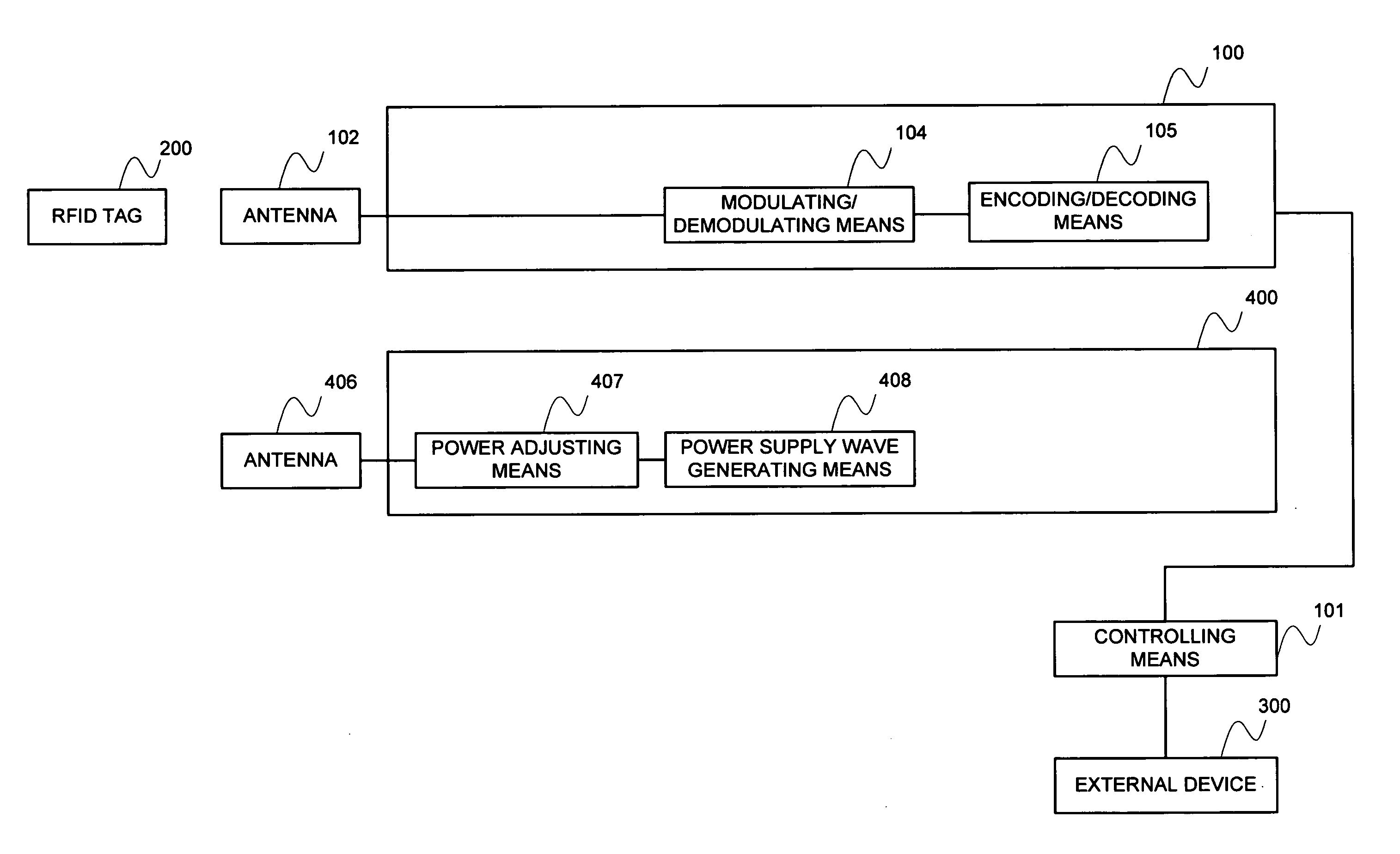
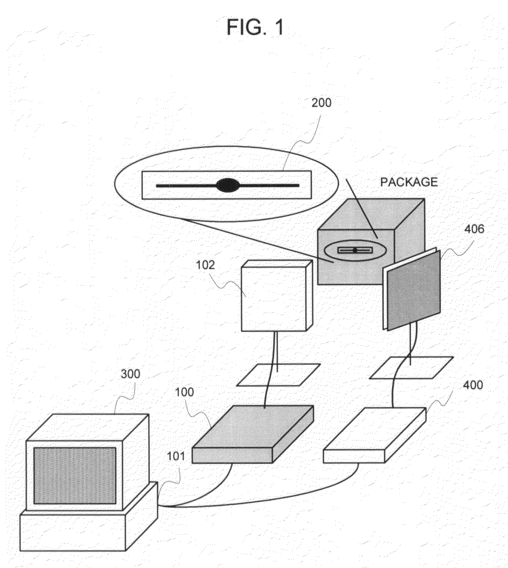
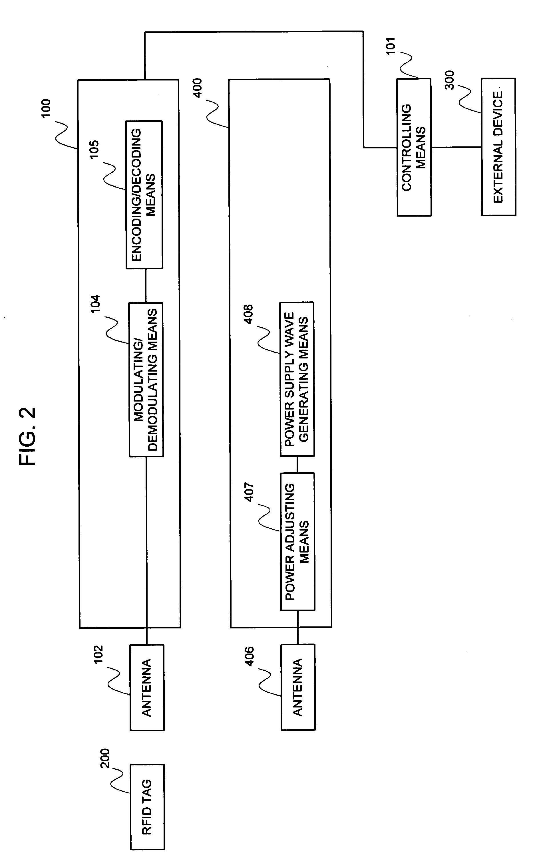
[0088]FIG. 1 is an appearance view of the RFID system in the first embodiment, and FIG. 2 is a block diagram of the RFID system in the first embodiment.

[0089]The RFID system in the first embodiment, as shown in FIG. 1, is configured of an RFID tag 200 for holding an ID attached to a package etc., receiving an interrogation wave from an antenna 102 and a power supply wave from an antenna 406, respectively, and transmitting an ID filed inside it as a response wave, a controlling means 101 for controlling an operation of each portion of a reader 100, an external device 300 for giving instruction to the controlling means 101, the reader 100 for transmitting the interrogation wave to the RFID tag 200, or reading off the response wave from the RFID tag 200 through the antenna 102, the antenna 102 for transmitting the interrogation wave from the reader 100, or receiving the response wave from the RFID tag 200, an antenna 406 for transmitting the p...

second embodiment

[0123]A second embodiment of the present invention will be explained.

[0124]The power of the power supply wave for supplying the power to the RFID tag 200 was changed in the first embodiment, and the power of the interrogation wave being transmitted to the RFID tag 200 is changed in the second embodiment, which differs from the first embodiment. Thereupon, as shown in FIG. 11, a power adjusting means 103 for adjusting a power of an interrogation wave is mounted onto the reader 100 instead of eliminating the power adjusting means 407 of the power supply device 400. Additionally, similarly to the first embodiment, the power supply device 400 and the reader 100 are not synchronized with each other for operation; however a configuration may be made so that the power supply device 400 and the reader 100 are synchronized with each other for operation.

[0125]Next, a flow of the process of the second embodiment of the present invention will be explained by employing FIG. 12.

[0126]At first, af...

third embodiment

[0140]A third embodiment will be explained.

[0141]FIG. 14 is an appearance view of the RFID system in the third embodiment, and FIG. 15 is a block diagram of the RFID system in the third embodiment.

[0142]The RFID system in the third embodiment, as shown in FIG. 14, is configured of an RFID tag 200 for holding the ID attached to a package etc., receiving an interrogation wave from an antenna 102 and a power supply wave from an antenna 406, and transmitting the ID filed inside it as a response wave, a controlling means 101 for controlling an operation of each portion of a reader 100 and an power supply device 400, an external device 300 for giving an instruction to the controlling means 101, the reader 100 for transmitting the interrogation wave to the RFID tag 200, or reading off the response wave from the RFID tag 200, an antenna 102 for transmitting the interrogation wave from the reader 100, or receiving the response wave from the RFID tag 200, the antenna 406 for transmitting the ...


PUM


Abstract

A reader (100) transmits an interrogation wave to a RFID tag (200) through an antenna (102) and receives a response wave from the RFID tag (200). A power supply device (400) generates a power supply wave to be supplied to the RFID tag, based on an instruction from a control means (101), and transmits the power supply wave to the RFID tag (200) while changing the output power of the generated power supply wave. The RFID tag (200) eliminates influences of its position and posture and surely obtains the optimum power supply conditions at least once.

Description

APPLICABLE FIELD IN THE INDUSTRY[0001]The present invention relates to an RFID system, and more particularly to an RFID system, a power supply device, and a power supply method, which enables an RFID tag to be detected at a high precision by transmitting an interrogation wave and a power supply wave to an RFID tag while changing at least one of a power of the them in transmitting them by employing a plurality of antennas.BACKGROUND ART[0002]In an RFID (Radio Frequency Identification) system that is configured of a device for holding an inherent identifier (ID) and a device for reading off it remotely through a radio wave, the system of reading off data of the RFID tag by transmitting a power and a read command to an ID holding device (RFID tag) from a reading device (reader) is called a passive-type RFID system.[0003]FIG. 21 illustrates an example of a general configuration of such an RFID system, and an example of an interrogation wave / a response wave that are exchanged between the...

Claims


Application Information

Patent Timeline
Patent Type & Authority Applications(United States)
IPC IPC(8): H04Q5/22
CPCG06K19/0701G06K19/0715H01Q1/2216H01Q1/22G06K19/0723
Inventor NAKAO, TOSHIYASU
Owner NEC CORP
Why Eureka
Try Eureka