Liquid ejection head
a liquid ejection head and liquid technology, applied in printing and other directions, can solve the problems of high probability of density unevenness, inability to accurately detect the density of liquid, and inability to form satellites, etc., and achieve the effect of stably affecting
- Summary
- Abstract
- Description
- Claims
- Application Information
AI Technical Summary
Benefits of technology
Problems solved by technology
Method used
Image
Examples
first embodiment
[0031]A first embodiment for carrying out the present invention will be described with reference to the attached drawings.
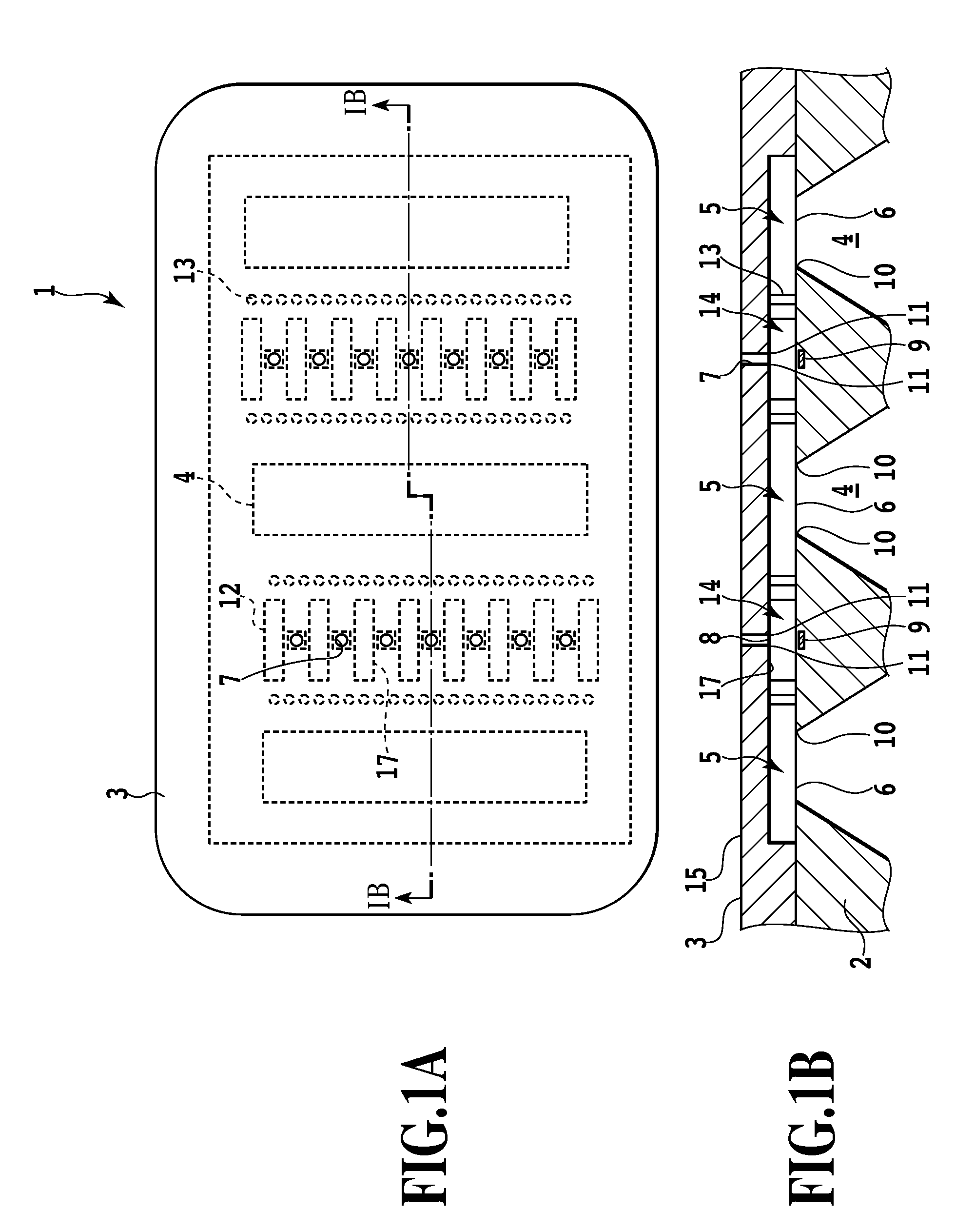
[0032]FIG. 1A is a plan view of a print head 1 as a liquid ejection head according to a first embodiment of the present invention. FIG. 1B is a sectional view of the print head taken along line IB-IB in FIG. 1A. In a print head according to the present embodiment, an orifice plate 3 is joined to a substrate 2. FIG. 1A shows a plan view of the orifice plate 3.
[0033]Ink supply ports 4 are formed as liquid supply ports in the substrate 2 so as to penetrate the substrate 2 from a back surface to a front surface thereof; ink is introduced into the print head 1 through the ink supply ports 4. To be fed to the interior of each of the ink supply ports 4 and thus into the print head 1, the ink is fed through the ink supply port 4 from the back surface to front surface of the substrate 2. In the present embodiment, the three ink supply ports 4 are formed along line IB-IB. ...
second embodiment
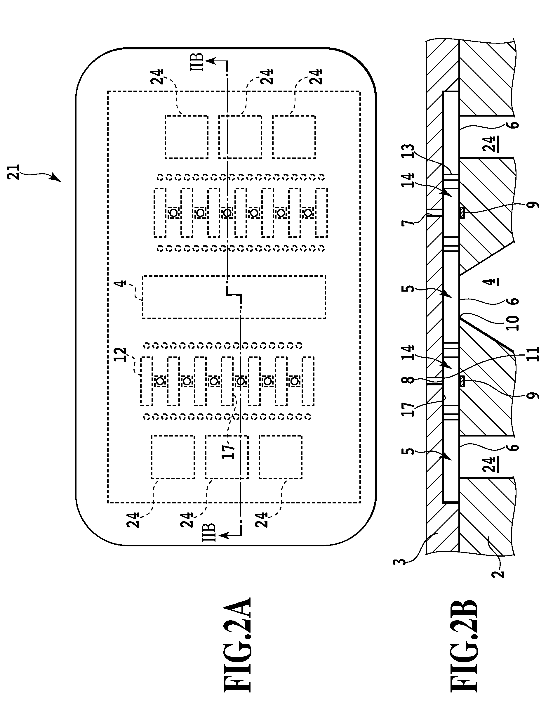
[0047]Now, a second embodiment will be described with reference to FIGS. 2A and 2B. In the figures, parts of the second embodiment which can be configured similarly to the corresponding ones of the first embodiment are denoted by the same reference numerals as those in the first embodiment. The description of these parts is omitted, and only the differences from the first embodiment will be described below.
[0048]FIG. 2A is a plan view of a print head 21 according to the second embodiment. FIG. 2B is a sectional view of the print head 21 taken along line IIB-IIB shown in FIG. 2A.
[0049]In the print head 1 according to the first embodiment, the three rows of the ink supply ports all extend in the same direction as that in which the row of the ejection ports extends and are formed continuously all over the length of the ink supply port in the longitudinal direction. In contrast, in the print head 21 according to the second embodiment, a plurality of segmented ink supply ports 24 are for...
third embodiment
[0056]Now, a third embodiment will be described with reference to FIGS. 3A and 3B. In the figures, parts of the third embodiment which can be configured similarly to the corresponding ones of the first and second embodiments are denoted by the same reference numerals as those in the first and second embodiments. The description of these parts is omitted, and only the differences from the first and second embodiments will be described below.
[0057]FIG. 3A is a plan view of a print head 31 according to the third embodiment. FIG. 3B is a sectional view of the print head 31 taken along line IIIB-IIIB shown in FIG. 3A.
[0058]In the first embodiment, described above, the three rows of the ink supply ports all extend in the same direction as that in which the row of the ejection ports extends and are formed continuously all over the length of the ink supply port in the longitudinal direction. Furthermore, in the second embodiment, the outside ones of the plurality of ink supply ports are eac...
PUM
 Abstract
Description
Claims
Application Information
 - R&D
- Intellectual Property
- Life Sciences
- Materials
- Tech Scout
- Unparalleled Data Quality
- Higher Quality Content
- 60% Fewer Hallucinations
Browse by: Latest US Patents, China's latest patents, Technical Efficacy Thesaurus, Application Domain, Technology Topic, Popular Technical Reports.
© 2025 PatSnap. All rights reserved.Legal|Privacy policy|Modern Slavery Act Transparency Statement|Sitemap|About US| Contact US: help@patsnap.com


