
Liquid crystal projector and control method for liquid crystal projector

a liquid crystal projector and control method technology, applied in optics, instruments, electrical devices, etc., can solve the problems of low light utilization efficiency and dark image displayed on the screen b>4/b>, and achieve the effect of enhancing the illumination of the displayed imag

Inactive Publication Date: 2009-02-12
SONY CORP
View PDF5 Cites 58 Cited by
  • Summary
  • Abstract
  • Description
  • Claims
  • Application Information

AI Technical Summary

Benefits of technology

[0025]Therefore, it is demanded to provide a liquid crystal projector and a driving method therefor wherein a 3D image can be displayed with an enhanced luminance.
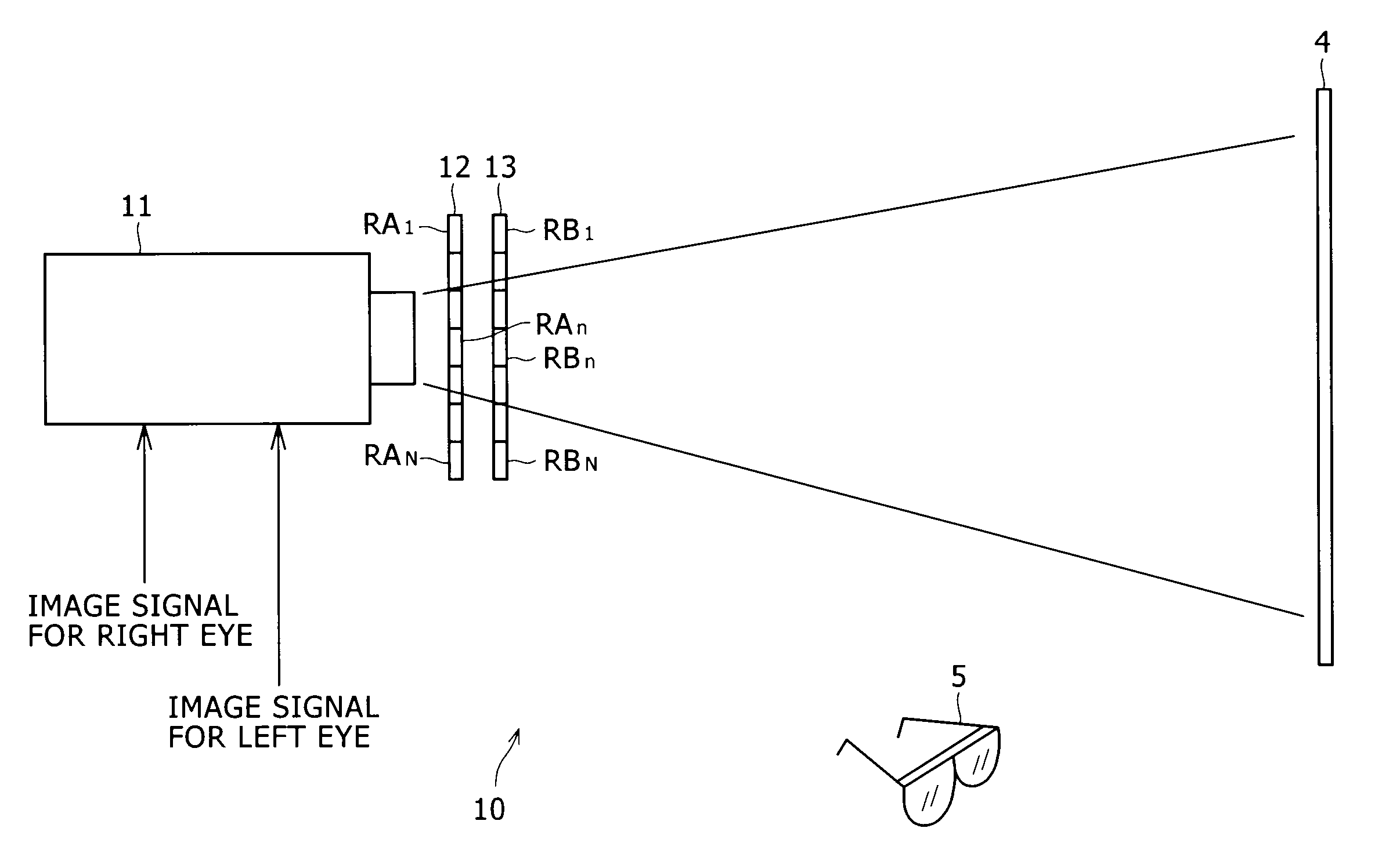
[0032]Consequently, with the liquid crystal projector and the control method for a liquid crystal projector, where the single liquid projector is used to display a 3D image, the luminance of the displayed image can be enhanced.

Problems solved by technology

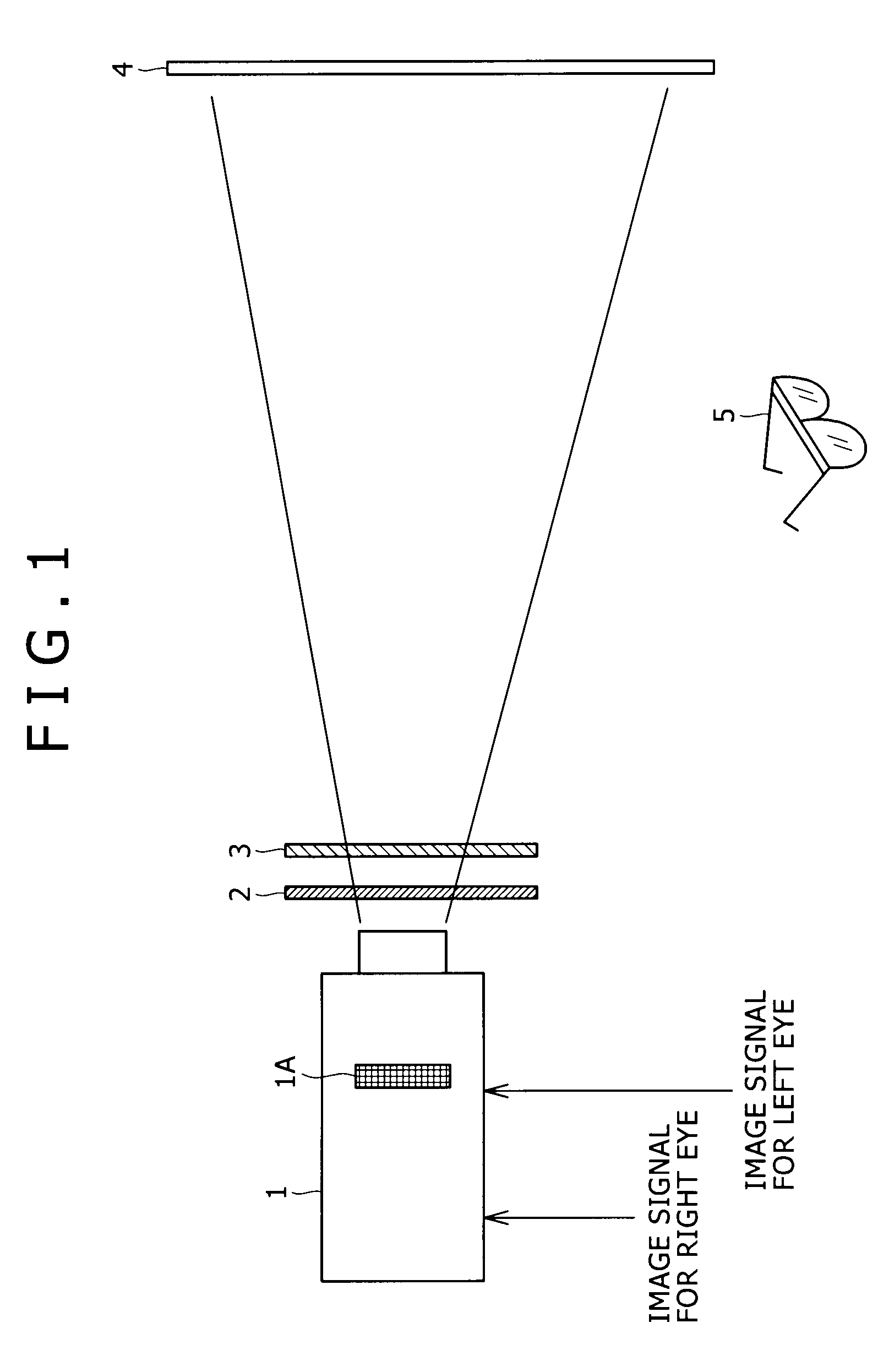
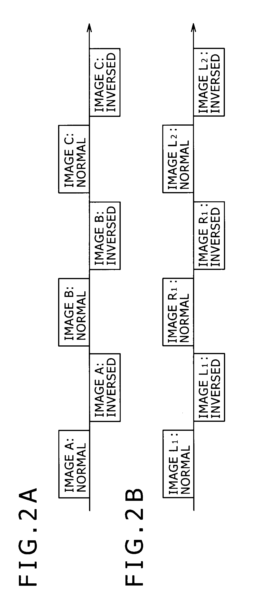
Therefore, the liquid crystal projector 1 in related art has a problem in that the image displayed on the screen 4 is dark.
Further, since the light source not shown in the liquid crystal projector 1 continues to emit light also while the optical shutter 2 is kept closed, the liquid crystal projector 1 in related art has another problem in that the utilization efficiency of light is low.

Method used


Image

  • Liquid crystal projector and control method for liquid crystal projector
  • Liquid crystal projector and control method for liquid crystal projector
  • Liquid crystal projector and control method for liquid crystal projector

Examples


Embodiment Construction

[0048]Before a preferred embodiment of the present invention is described in detail, a corresponding relationship between several features recited in the accompanying claims and particular elements of the preferred embodiment described below is described. The description, however, is merely for the confirmation that the particular elements which support the invention as recited in the claims are disclosed in the description of the embodiment of the present invention. Accordingly, even if some particular element which is recited in description of the embodiment is not recited as one of the features in the following description, this does not signify that the particular element does not correspond to the feature. On the contrary, even if some particular element is recited as an element corresponding to one of the features, this does not signify that the element does not correspond to any other feature than the element.

[0049]According to an embodiment of the present invention, there is...


PUM


Abstract

A liquid crystal projector which projects a three-dimensional imaged based on image signals for the left and right eyes including: a liquid crystal panel into which an image for the left or right eye is written in a one-field time period based on the image signal; an optical shutter has a plurality of divisional regions arranged in a vertical direction and controllable independently in regard to whether or not light should be blocked; a polarizing element has a plurality of divisional regions arranged in vertical direction and controllable independently in regard to whether the polarization direction should be set to that for the left eye or the right eye; and a control circuit controls the optical shutter and the polarizing element in synchronism with a writing position in the liquid crystal panel.

Description

CROSS REFERENCES TO RELATED APPLICATIONS[0001]The present invention contains subject matter related to Japanese Patent Application JP 2007-205081 filed in the Japan Patent Office on Aug. 7, 2007, the entire contents of which being incorporated herein by reference.BACKGROUND OF THE INVENTION[0002]1. Field of the Invention[0003]This invention relates to a liquid crystal projector and a control method for a liquid crystal projector, and more particularly to a liquid crystal projector and a control method for a liquid crystal projector suitable for use to display a three-dimensional image.[0004]2. Description of the Related Art[0005]An image shown on a screen in a movie theater was heretofore taken using a film and shown from the film. Recently, however, as is called digital cinema, an image is recorded in the form of a digital signal and transmitted as an image signal to individual movie theaters, and in each movie theater, the image is shown on a screen using the image signal.[0006]In...

Claims


Application Information

Patent Timeline
IPC IPC(8): H04N13/02
CPCH04N13/0434H04N13/0497H04N13/0459H04N13/0438H04N13/337H04N13/341H04N13/363H04N13/398
Inventor TOMITA, HIDEOIWAI, JUNICHI
Owner SONY CORP
Learn More