Time-Multiplexed Multi-Output DC/DC Converters and Voltage Regulators

a multi-output dc/dc converter and voltage regulator technology, applied in the direction of electric variable regulation, process and machine control, instruments, etc., can solve the problems of low power dissipation in the switch, unfavorable unity transfer characteristic of boost converter, and unwanted stray

Inactive Publication Date: 2009-02-12
ADVANCED ANALOGIC TECHNOLOGIES INCORPORATED
View PDF0 Cites 31 Cited by
  • Summary
  • Abstract
  • Description
  • Claims
  • Application Information

AI Technical Summary

Benefits of technology

[0030]The converter just described operates as a boost converter. The voltage produced by each output stage exceeds the supply voltage. Typically, each output stage will produce a different output voltage so the converter operates as a series of two or more boost converters. It is also possible to implement an inverting converter using a related topology. A typical implementation of the inverting converter includes an inductor is connected between ground and a node Vx. A low-side switch connects the node Vx and an input supply (typically a battery). Two or more output stages

Problems solved by technology

Excepting switching transients, the ID·VDS product in the power MOSFET remains small, and power dissipation in the switch remains low.
The disadvantage of transformers is they are large compared to single-winding inductors and suffer from unwanted stray inductances.
While this equation describes a wide range of conversion ratios, the boost converter cannot smoothly approach a unity transfer characteristic without requiring extremely fast devices and circuit response times. For high duty factors and conversion ratios, the inductor conducts large spikes of current and degrades efficiency.
Space limitations preclude the use of so many switching regulators each with separ

Method used


Image

  • Time-Multiplexed Multi-Output DC/DC Converters and Voltage Regulators
  • Time-Multiplexed Multi-Output DC/DC Converters and Voltage Regulators
  • Time-Multiplexed Multi-Output DC/DC Converters and Voltage Regulators

Examples


Embodiment Construction

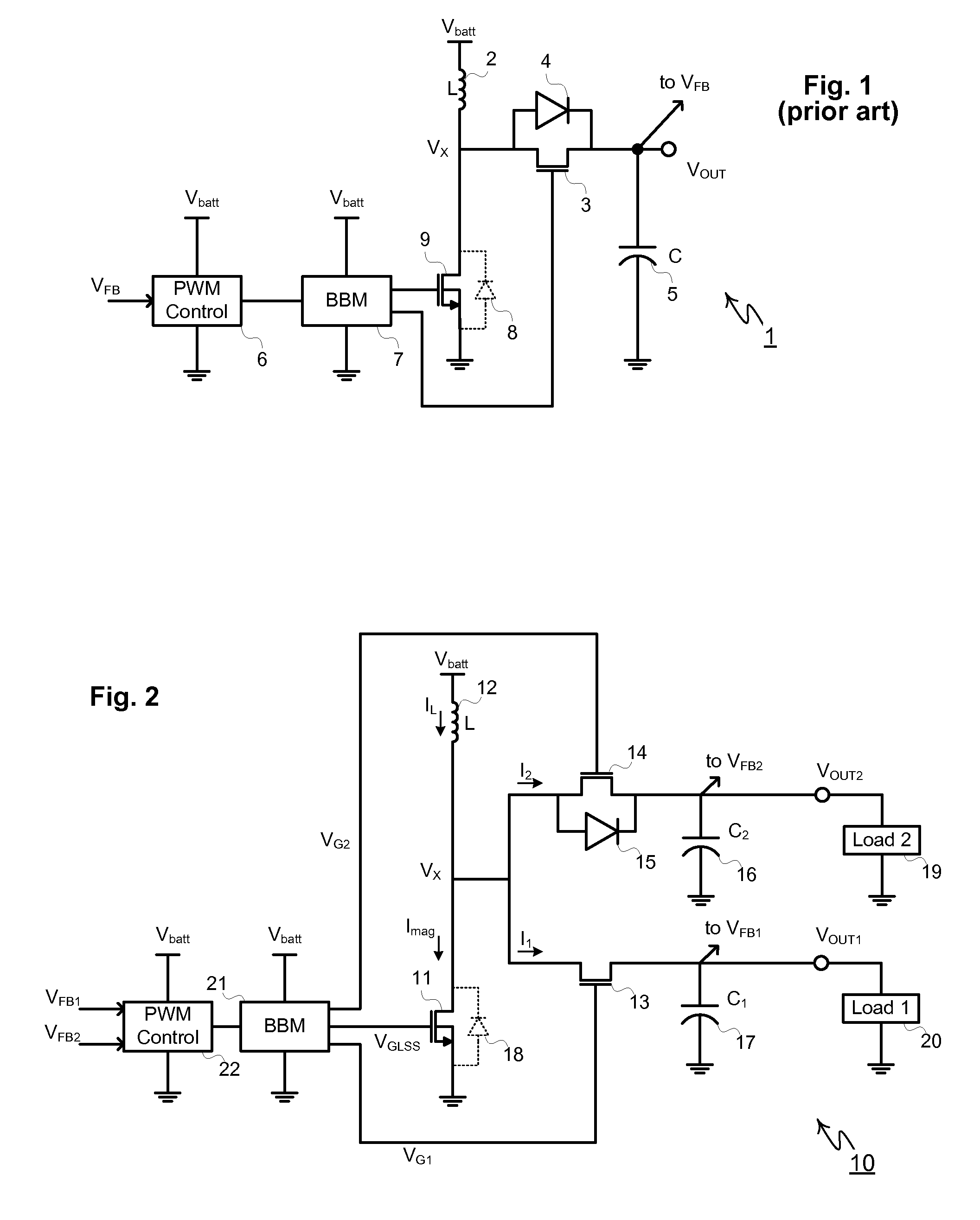
[0052]As described previously, conventional non-isolated switching regulators require one single-winding inductor and corresponding dedicated PWM controller for each regulated output voltage. In contrast, this disclosure describes an inventive boost converter able to produce multiple independently-regulated outputs from one single-winding inductor.

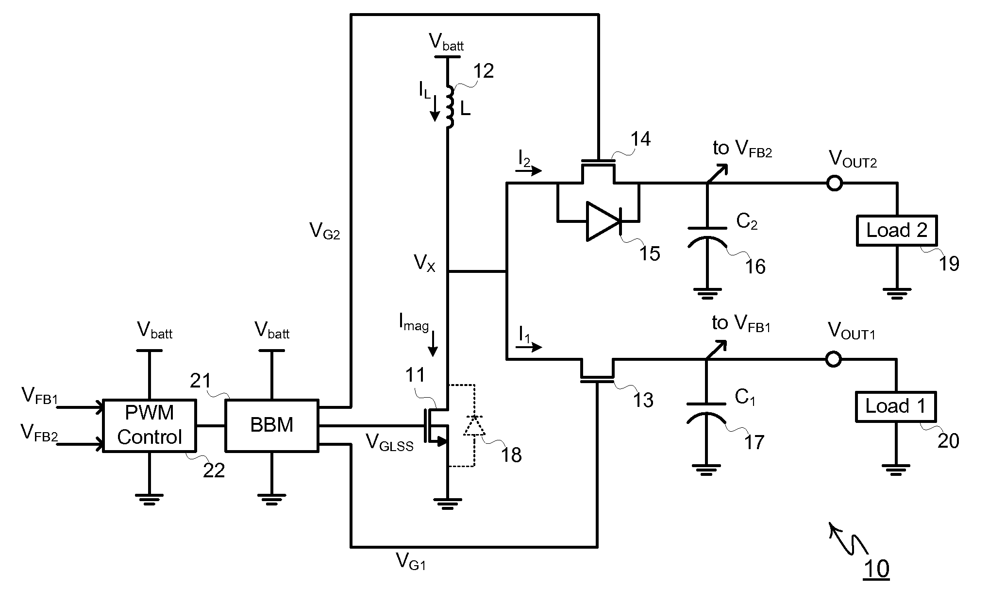
[0053]Shown in FIG. 2 for a two-output version, time-multiplexed-inductor boost converter 10 comprises low-side N-channel MOSFET 11, inductor 12, floating synchronous rectifier 14 with intrinsic source-to-drain diode 15, floating synchronous rectifier 13 with no source-to-drain diode, output filter capacitors 17 and 16 filtering outputs VOUT1 and VOUT2 and driving loads 20 and 19 respectively. Regulator operation is controlled by PWM-controller 22 driving break-before-make buffer 21, also referred to by the acronym BBM which in turn controls the on-time of MOSFETs 11, 13, and 14. PWM controller 22 may operate at fixed or variable frequency...


PUM


Abstract

A boost switching converter with multiple outputs includes an inductor is connected between an input supply (typically a battery) and a node Vx. A low-side switch connects the node Vx and ground. Two or more output stages are included. Each output stage includes a high-side switch and an output capacitor. Each output stage is connected to deliver electrical current to a respective load. A control circuit is connected to drive the low-side switch and high-side switches in a repeating sequence. The inductor is first charged and then discharged into each output stage. In effect, a series of different switching converters are provided, each with a different output voltage.

Description

BACKGROUND OF THE INVENTION[0001]Voltage regulation is commonly required to prevent variation in the supply voltage powering various microelectronic components such as digital ICs, semiconductor memory, display modules, hard disk drives, RF circuitry, microprocessors, digital signal processors and analog ICs, especially in battery powered application likes cell phones, notebook computers and consumer products.[0002]Since the battery or DC input voltage of a product often must be stepped-up to a higher DC voltage, or stepped-down to a lower DC voltage, such regulators are referred to as DC-to-DC converters. Step-down converters are used whenever a battery's voltage is greater than the desired load voltage. Step-down converters may comprise inductive switching regulators, capacitive charge pumps, and linear regulators. Conversely, step-up converters, commonly referred to boost converters, are needed whenever a battery's voltage is lower than the voltage needed to power its load. Step-...

Claims


Application Information

Patent Timeline
IPC IPC(8): H02M3/335
CPCH02M3/1588Y02B70/1466H02M2001/009H02M1/009Y02B70/10
Inventor WILLIAMS, RICHARD K.
Owner ADVANCED ANALOGIC TECHNOLOGIES INCORPORATED
Why Eureka
Try Eureka