Sil near-field system

Inactive Publication Date: 2009-02-12
SAMSUNG ELECTRONICS CO LTD
View PDF2 Cites 20 Cited by
  • Summary
  • Abstract
  • Description
  • Claims
  • Application Information

AI Technical Summary

Benefits of technology

[0012]Aspects of the present invention provide an SIL near-field system having a longer working distance by using an incident

Problems solved by technology

However, such a conventional optical storage method cannot satisfy future storage capacity requirements.
The small air gap, that is, a

Method used


Image

  • Sil near-field system
  • Sil near-field system
  • Sil near-field system

Examples


Example

[0049]Reference will now be made in detail to the present embodiments of the present invention, examples of which are illustrated in the accompanying drawings, wherein like reference numerals refer to the like elements throughout. The embodiments are described below in order to explain the present invention by referring to the figures.

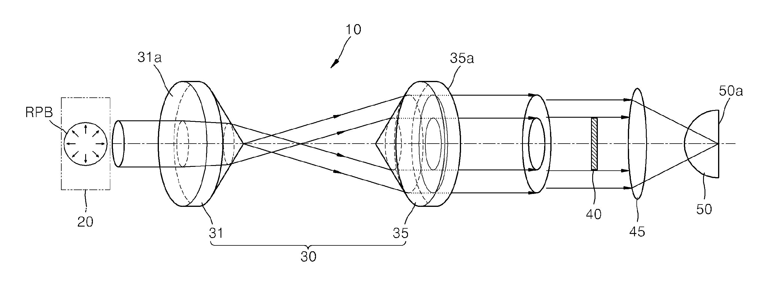
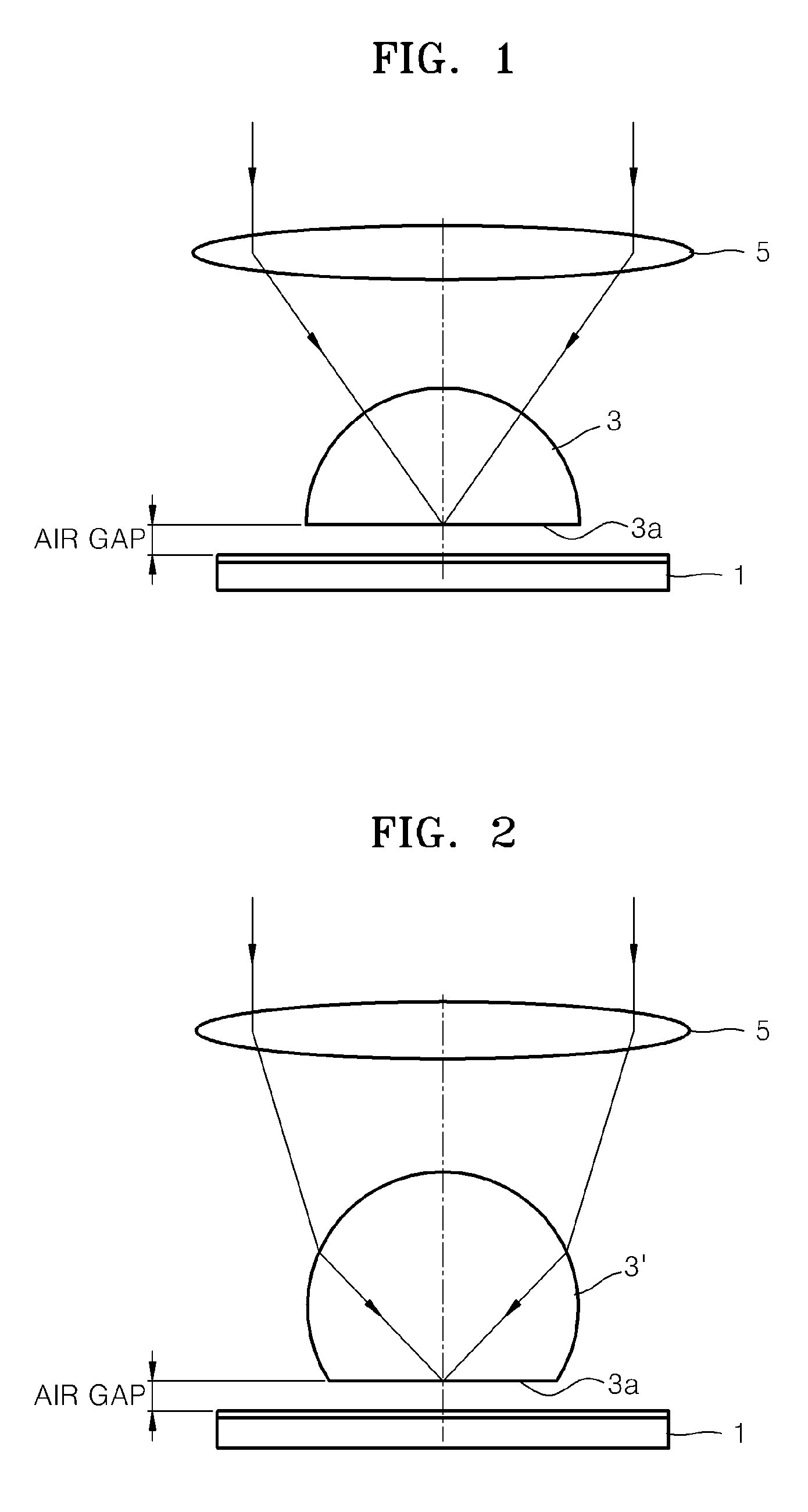
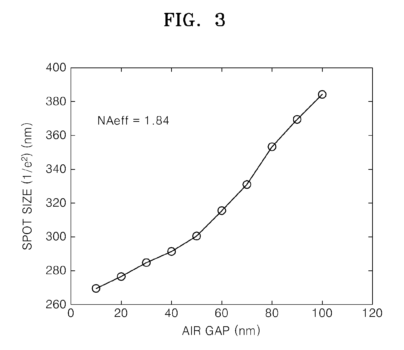
[0050]A near-field recording using an SIL can realize a high recording density using a lens having a high effective numerical aperture (NA). However, an air gap existing between the SIL and a recording medium must be maintained within a range of 20 to 30 nm due to a rapid increase in a spot size and a decay of an evanescent wave, which results in the need for a strict gap servo and a tight tilt margin.

[0051]In a general near-field system having the SIL, a linearly polarized beam or a circularly polarized beam is used as an incident beam. FIG. 4 shows the linearly polarized beam, and FIG. 5 shows the circularly polarized beam. The linear polarization an...


PUM


Abstract

A solid immersion lens (SIL) near-field system including: a radially polarized beam generator to generate a radially polarized beam; an SIL; an objective lens to focus the radially polarized beam on a bottom surface of the SIL; and a mask to shield a center portion of the radially polarized beam, the center portion being about an optical axis of the radially polarized beam.

Description

CROSS-REFERENCE TO RELATED APPLICATIONS[0001]This application claims the benefit of Korean Patent Application No. 2007-80843, filed on Aug. 10, 2007, in the Korean Intellectual Property Office, the disclosure of which is incorporated herein by reference.BACKGROUND OF THE INVENTION[0002]1. Field of the Invention[0003]Aspects of the present invention relate to a solid immersion lens (SIL) near-field system, and more particularly, to an SIL near-field system having a long working distance so as to sufficiently control a gap to prevent the SIL and a disc surface from colliding with each other in the near-field system.[0004]2. Description of the Related Art[0005]In order to increase a storage capacity of a recording medium, research to develop multilayer recording media using a laser beam of a short wavelength and an objective lens having a high numerical aperture (NA) is being performed. As a result of such research, Blu-ray discs, having a storage capacity of 25 GB for each layer in it...

Claims


Application Information

Patent Timeline
IPC IPC(8): G11B7/00G02B3/00G02B5/30G02B3/02G11B7/135
CPCG02B27/288G11B7/0908G11B2007/13727G11B7/1387G11B7/1398G11B7/1378G11B7/1372G11B7/1381
Inventor HONG, TAOKIM, TAE-KYUNGLEE, JIN-KYUNG
Owner SAMSUNG ELECTRONICS CO LTD
Why Eureka
Try Eureka