Lighting assembly with high irradiance

Active Publication Date: 2020-06-11
LUMILEDS
View PDF0 Cites 1 Cited by
  • Summary
  • Abstract
  • Description
  • Claims
  • Application Information

AI Technical Summary

Benefits of technology

[0004]It is an object of the present invention to provide

Problems solved by technology

While traditional mercury vapor lamps can be replaced in certain low UV intensity applications with LED based UV curing systems, it is more difficult to use LEDs as a replacement for high intensity applications.
LED sources and LED

Method used


Image

  • Lighting assembly with high irradiance
  • Lighting assembly with high irradiance
  • Lighting assembly with high irradiance

Examples


Embodiment Construction

[0046]Various embodiments of the invention will now be described by means of the Figures.

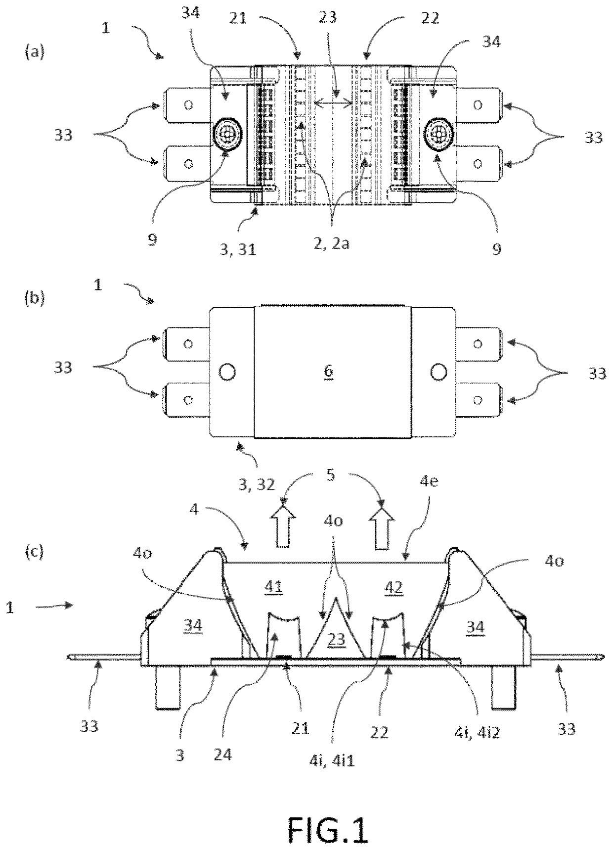
[0047]FIG. 1 shows a principle sketch of the lighting module according to the present invention (a) in a top view onto the front side, (b) in a top view onto the backside, and (c) in a side view. The lighting module 1 comprises two rows 21, 22 of eleven LEDs 2 each which are closely packed. The rows are separated from each other by an intermediate area 23 between the rows 21, 22. The rows 21, 22 are arranged parallel to each other on a front side 31 of a printed circuit board 3 further comprising electrical contacts 33 to operate the rows of LEDs. The printed circuit board 3 might be fixed to another substrate, holder or housing (not shown here) by screws 9 or other fixing means. The lighting module 1 further comprises one integral optical element 4 on top of the LEDs 2 in order to shape light 5 emitted from each of the multiple LEDs 2, where the optical element 4 comprises one collimator lens p...


PUM


Abstract

A lighting module and a lighting assembly provide high irradiance at long working distances. The lighting module includes at least two rows of multiple LEDs separated from each other by an intermediate area between the rows and one integral optical element on top of the at least two rows of multiple LEDs. The one integral optical element includes one collimator lens portion per row of LEDs extending along the row of LEDs. The collimator lens portions of different rows are merged together above the intermediate area. The collimator lens portions, seen in a direction perpendicular to the at least two rows, provide an off-axis focus for the one collimator lens portion, and focus light emitted from the at least two rows of multiple LEDs in a focus line extending parallel to the rows of LEDs at a focus distance above the optical element.

Description

FIELD OF THE INVENTION[0001]The invention relates to a lighting module providing a high irradiance at a long working distance, a lighting assembly comprising multiple lighting modules, methods to manufacture the lighting module as well as the lighting assembly and use of the lighting modules or lighting assemblies.BACKGROUND OF THE INVENTION[0002]UV curing technology is utilized for curing inks, coatings, adhesives and other commercially useful UV sensitive materials through polymerization. While traditional mercury vapor lamps can be replaced in certain low UV intensity applications with LED based UV curing systems, it is more difficult to use LEDs as a replacement for high intensity applications. LED sources and LED systems have a relatively low output power compared to mercury-arc lamps. LED arrays are used at very close range to the material which poses the risks of the curing system coming into contact with the substrate that is being cured.[0003]Consequently, there is a need f...

Claims


Application Information

Patent Timeline
IPC IPC(8): H05K1/18H01L33/60H01L27/15H05K1/02
CPCH05K1/021H01L27/153H05K2201/10121H05K1/181H01L33/60H05K2201/10106G02B19/0066G02B19/0028
Inventor ENGELEN, ROBSTASSAR, EMANUEL
Owner LUMILEDS
Why Eureka
Try Eureka