Ultraviolet irradiation apparatus

A technology of irradiating device and ultraviolet light, applied in the direction of lighting device, lighting device components, circuit layout, etc., can solve problems such as control circuit obstacles, and achieve the effect of improving applied voltage, high reliability, and preventing electromagnetic noise

Active Publication Date: 2013-09-25
ORC MFG
View PDF2 Cites 0 Cited by
  • Summary
  • Abstract
  • Description
  • Claims
  • Application Information

AI Technical Summary

Problems solved by technology

As another problem, since the AC rectangular wave voltage flows through the wires, electromagnetic noise waves are radiated to the outside through the wires, causing obstacles to the control circuit inside the housing.
In addition, it also causes electromagnetic noise waves to propagate through the power line to the commercial line

Method used


Image

  • Ultraviolet irradiation apparatus
  • Ultraviolet irradiation apparatus

Examples


Embodiment Construction

[0022] Hereinafter, embodiments of the present invention will be described with reference to the drawings.

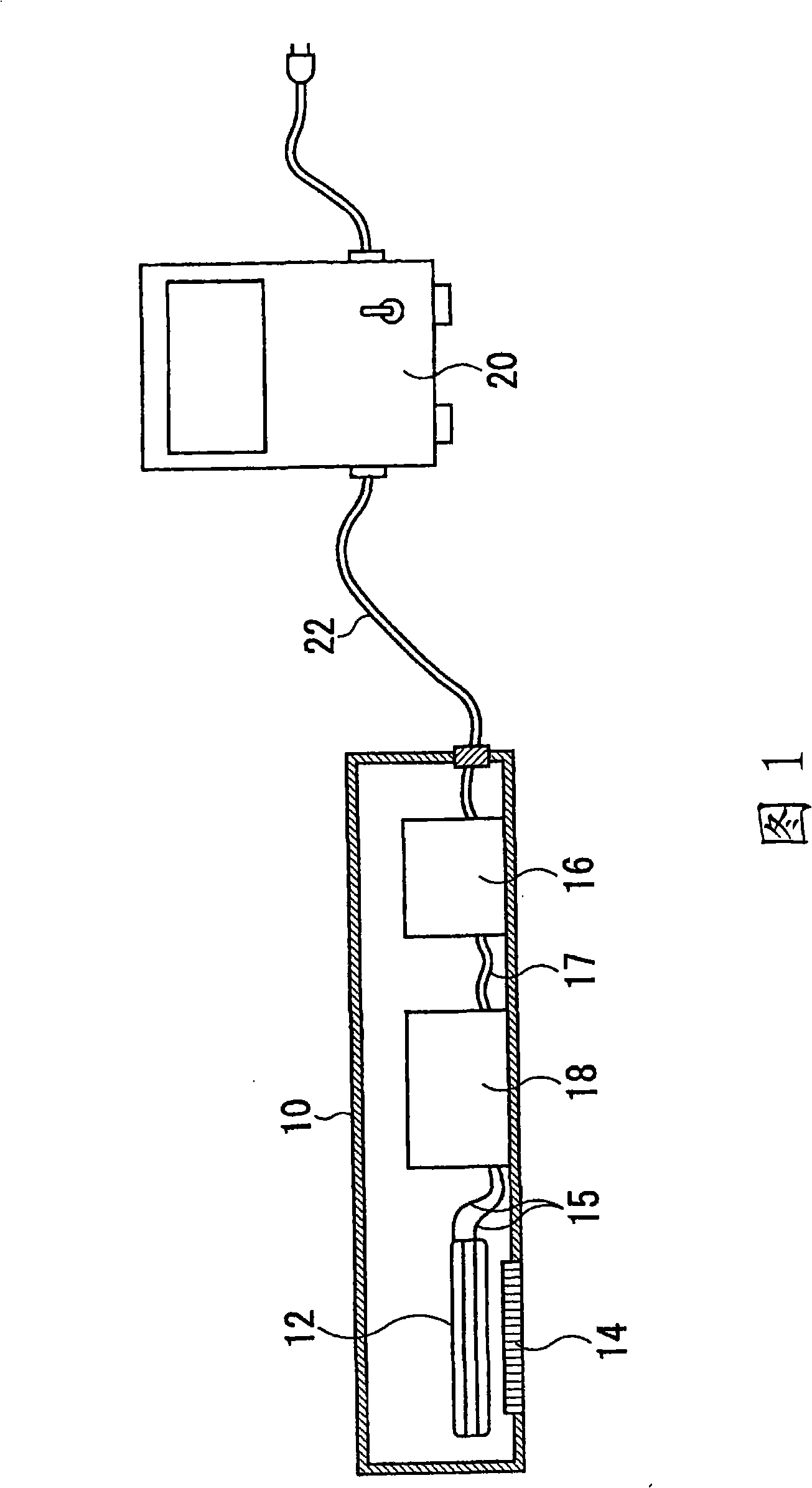
[0023] figure 1 It is a figure which schematically shows the ultraviolet irradiation apparatus of 1st Embodiment.

[0024] The ultraviolet irradiation device has a globe 10 made of a metal frame, and a discharge lamp 12 is provided inside the globe 10 . The discharge lamp 12 is a dielectric barrier discharge lamp made of synthetic quartz glass and has a double cylindrical shape. That is, an inner tube and an outer tube (both not shown) constituting a dielectric barrier are arranged coaxially, and a hollow cylindrical discharge space is formed between them.

[0025] A conductive mesh electrode (not shown) that can transmit light is provided on the outer surface of the outer tube, and a thin film electrode (not shown) is provided on the inner side of the inner tube. A rare gas or a mixed gas of a rare gas and a halogen gas is enclosed in the discharge space. The irrad...


PUM


Abstract

An ultraviolet irradiation apparatus of using dielectric impedance discharge lamp for preventing electromagnetic noise produced by the ultraviolet radiation from radiating all around of spreading to exterior via cables. Inside the lampshade (10) of electric lamp (12) is provided with switch circuit (16) for converting DC constant voltage into high-frequency ac voltage; and booster transformer (18) of using high-frequency ac voltage to boost voltage. Low-voltage direct-current power supply (20) is provided exterior of the lampshade (10) and connected with the lampshade (10) via cables (22).

Description

technical field [0001] The present invention relates to an ultraviolet irradiation device mainly for industrial use, and particularly to a device using a dielectric barrier discharge excimer lamp or the like. Background technique [0002] As a light source used in the above-mentioned industrial ultraviolet irradiation device, for example, there is a xenon excimer lamp with a luminous wavelength of 172 nm described in Patent Document 1, which is often used for dry cleaning (dry cleaning) of substrates for liquid crystal panels. cleaning) etc. Excimer lamps often employ a lamp having a double-tube structure, and the light-emitting part thereof extends in a tubular shape along the axial direction. When cleaning the substrate, the substrate to be irradiated moves on the conveyor belt at a constant speed, and the lamp is installed slightly above the substrate in a direction perpendicular to the conveying direction of the conveyor belt. The entire width of the object to be irrad...

Claims


Application Information

Patent Timeline
Patent Type & Authority Patents(China)
IPC IPC(8): F21S2/00F21V23/00H05B41/02H01J65/04
Inventor 安田诚小林刚篠木晟金子仁志
Owner ORC MFG
Why Eureka
Try Eureka