
Film Forming Apparatus and Film Forming Method

a film forming apparatus and film forming technology, applied in the direction of vacuum evaporation coating, chemical vapor deposition coating, coating, etc., can solve the problems of difficult to increase the film formation rate, no proposal at all about quickly, and difficult to uniformly provide the film thickness and so on over the whole area of the substrate, so as to minimize remaining and deposition of molecules, and quick and smooth transition

Inactive Publication Date: 2009-02-12
TOKYO ELECTRON LTD +1
View PDF5 Cites 16 Cited by
  • Summary
  • Abstract
  • Description
  • Claims
  • Application Information

AI Technical Summary

Benefits of technology

[0012]In the film forming apparatus and the film forming method proposed in Patent Document 2, since it is possible to suppress generation of organic contaminants and material-decomposed / dissociated matters that adversely affect the properties of a film forming material, a high-quality thin film can be deposited. Therefore, when such a film forming apparatus and film forming method are applied to formation of an organic EL device, it is possible to obtain a high-quality organic EL device with a high brightness and a long lifetime.

Problems solved by technology

On the other hand, according to Patent Document 2when a substrate to be subjected to film formation has a large area, it is difficult to uniformly provide the film thickness and so on over the whole area of the substrate.
Further, it is difficult to increase the film formation rate to thereby perform film formation efficiently.
However, no proposal has been offered at all about quickly and smoothly switching an atmosphere according to the process, that is, about means for quickly performing a state transition.
Therefore, it is difficult to form an organic EL thin film at high rate.

Method used


Image

  • Film Forming Apparatus and Film Forming Method
  • Film Forming Apparatus and Film Forming Method
  • Film Forming Apparatus and Film Forming Method

Examples


Embodiment Construction

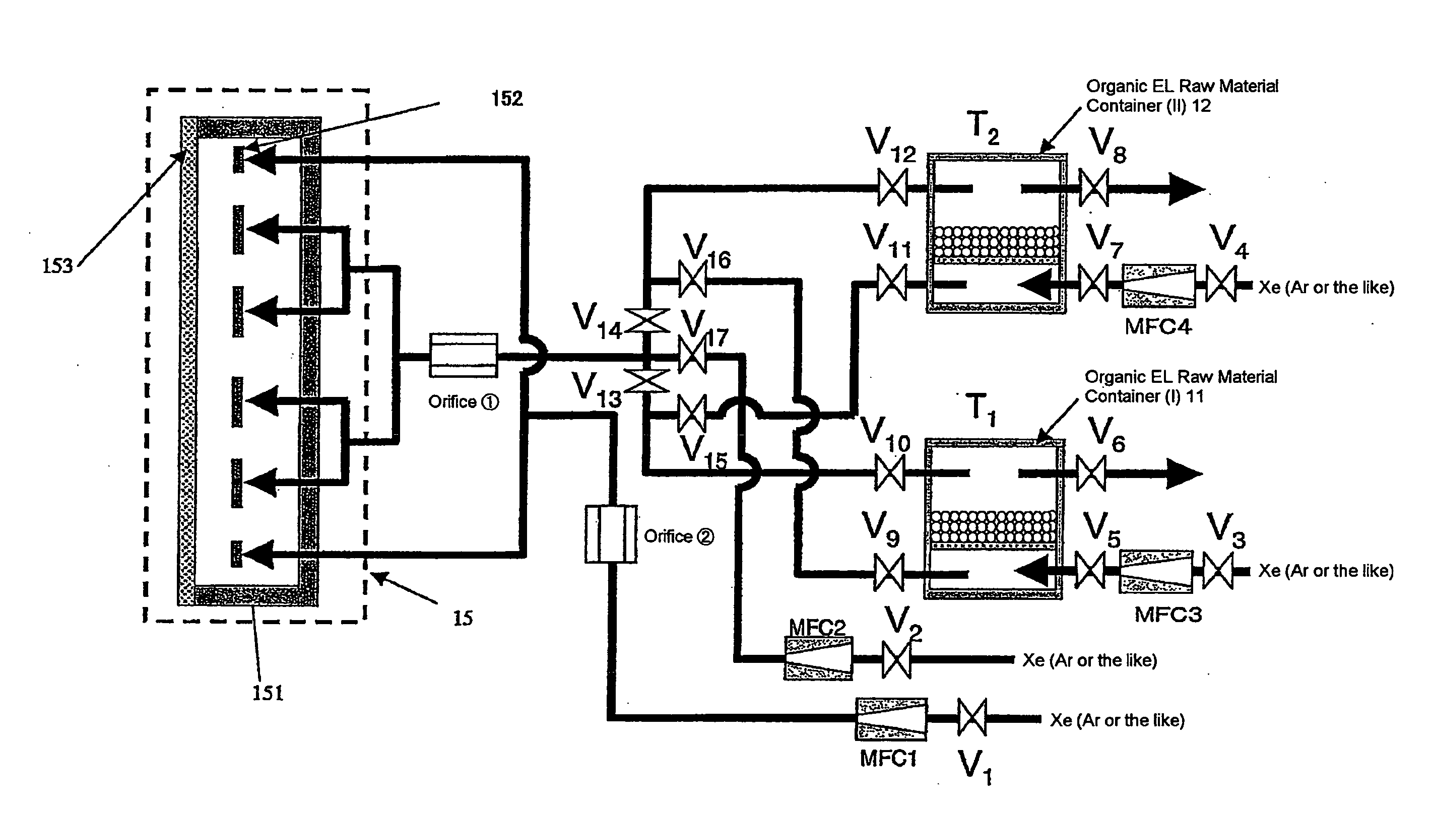
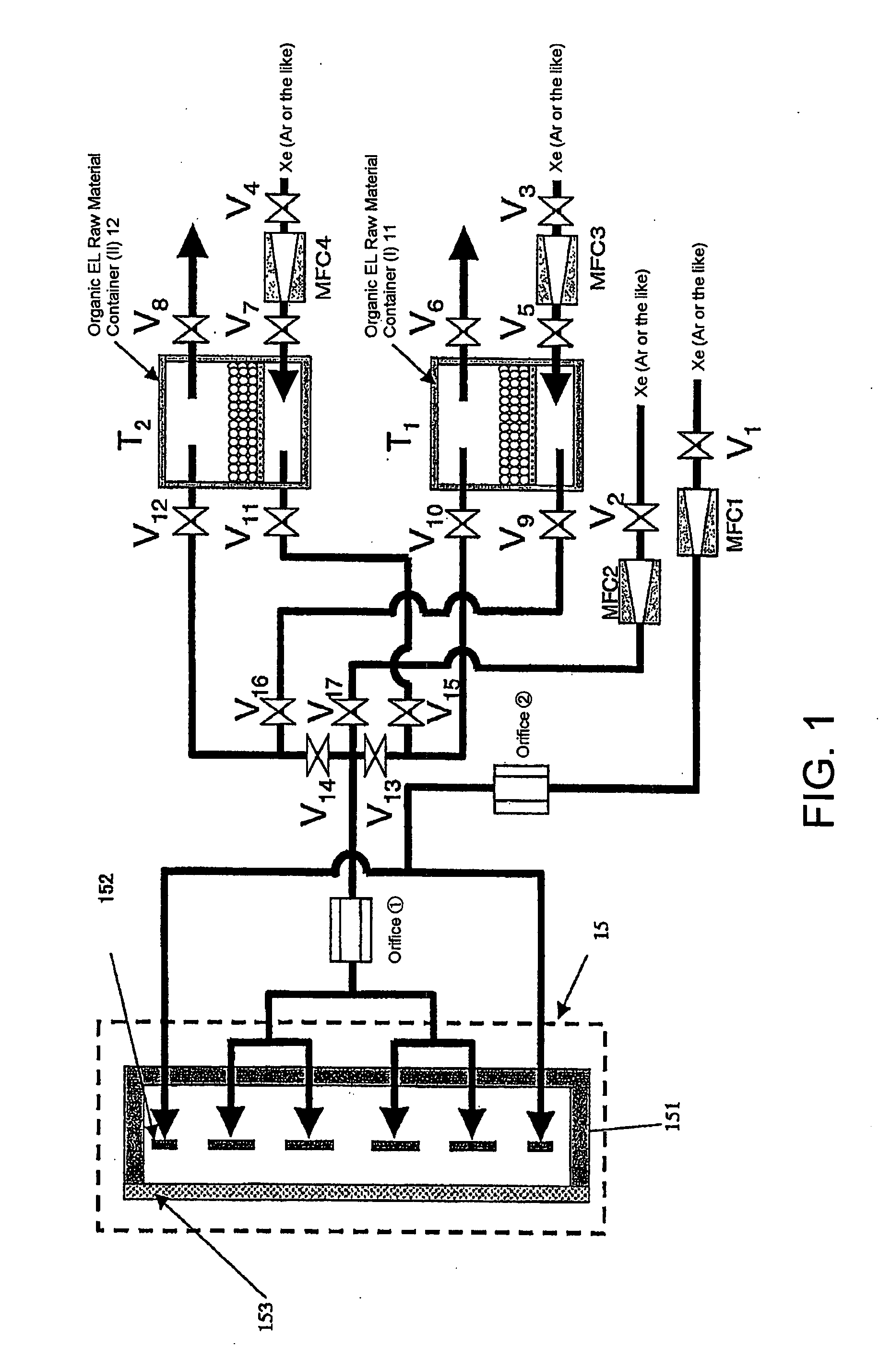
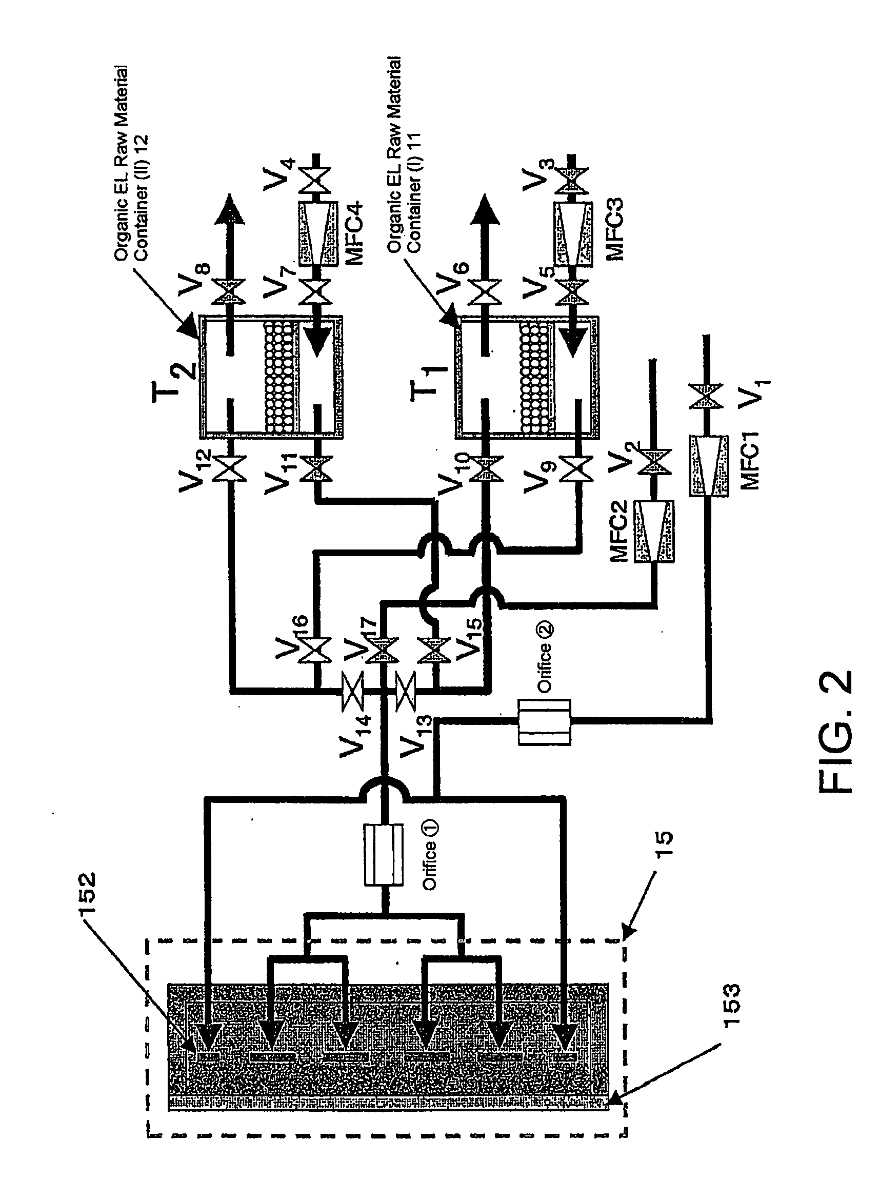
[0038]Referring to FIG. 1, a film forming apparatus according to one embodiment of this invention is shown, wherein there is illustrated a film forming apparatus for forming an organic EL film (e.g. Alq3(8-hydroxyquinoline aluminum) being a light emitting layer, NPD(C44H32N2)) being a hole transport layer, or the like). The illustrated film forming apparatus is an apparatus for forming a single organic EL film and comprises two organic EL raw material containers (I) 11 and (II) 12 and an ejection vessel 15 for ejecting organic EL molecules onto a substrate of glass or the like (not shown). The two organic EL raw material containers 11 and 12 and the ejection vessel 15 are connected to each other by a piping system (i.e. flow paths) according to this invention. In the case of forming a plurality of organic EL films, the same structure is provided for a raw material of each organic EL film.

[0039]An organic compound molecule ejection apparatus 151 is disposed in the ejection vessel 15....


PUM

PropertyMeasurementUnit
Temperatureaaaaaaaaaa
Timeaaaaaaaaaa
Pressureaaaaaaaaaa

Abstract

In an apparatus for film formation, constituted so that an organic EL molecular gas is ejected into an ejection vessel, a plurality of organic EL material vessels are provided together with a piping system for connecting the plurality of organic EL material vessels to the ejection vessel. The plurality of organic EL material vessels are selectively put into a supply state of organic EL molecules. The piping system is constructed so that the carrier gas is fed into each organic EL material vessel in such a manner that the pressure during film formation and the pressure during non-film formation are equal to each other. During non-film formation, the carrier gas is allowed to flow from one of the organic EL material vessels to other material vessel.

Description

TECHNICAL FIELD[0001]This invention relates to a film forming apparatus and a film forming method for forming a layer of a predetermined material and, in particular, relates to a film forming apparatus and a film forming method for forming a layer of a predetermined material by evaporating a raw material of the predetermined material.BACKGROUND ART[0002]A method of forming a layer of a predetermined material by evaporating a raw material of a predetermined material is widely used in the manufacture of semiconductor devices, flat panel display devices, and other electronic devices. Description will be restricted hereinbelow to an organic EL display device as one example of those electronic devices. If such an organic EL display device could have a sufficient brightness and a long lifetime, such as several tens of thousands of hours or more, the organic EL display device could implement an ideal flat panel display because the organic EL display device uses organic EL elements of a sel...

Claims


Application Information

Patent Timeline
IPC IPC(8): B05D5/06C23C16/455
CPCC23C14/12C23C14/228C23C14/24H01L51/56H01L51/0008H01L51/0081C23C14/564H10K71/16H10K85/324H10K71/00
Inventor OHMIMATSUOKA, TAKAAKINAKAYAMA, SHOZOITO, HIRONORI
Owner TOKYO ELECTRON LTD
Learn More