Reliquifier and recondenser

a reliquifier and condenser technology, applied in the field of gas liquefaction, reliquefaction and recondensation with pulse tube cryocoolers, can solve the problems of wear of the seals on the displacer, increasing prices, and increasing the cost of maintenance and replacemen

Active Publication Date: 2009-02-26
CRYOMECH
View PDF13 Cites 23 Cited by
  • Summary
  • Abstract
  • Description
  • Claims
  • Application Information

AI Technical Summary

Problems solved by technology

With growing demand for helium worldwide and increased pressure on suppliers resulting in greatly increased prices, it is becoming evident that the world's helium supply is finite and irreplaceable.
The noise and vibration induced by the displacer creates problems, and the wear of the seals on the displacer require periodic maintenance and replacement.
These result in high reliability,

Method used


Image

  • Reliquifier and recondenser
  • Reliquifier and recondenser
  • Reliquifier and recondenser

Examples


Embodiment Construction

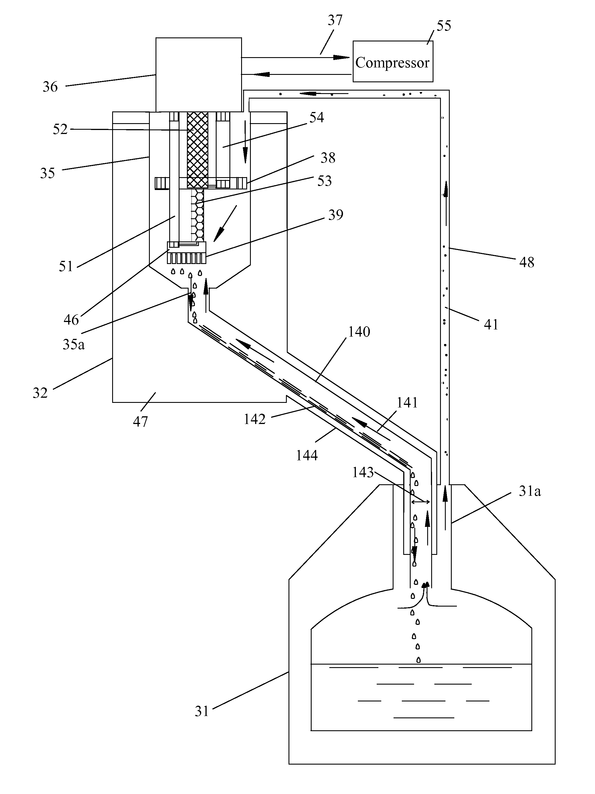
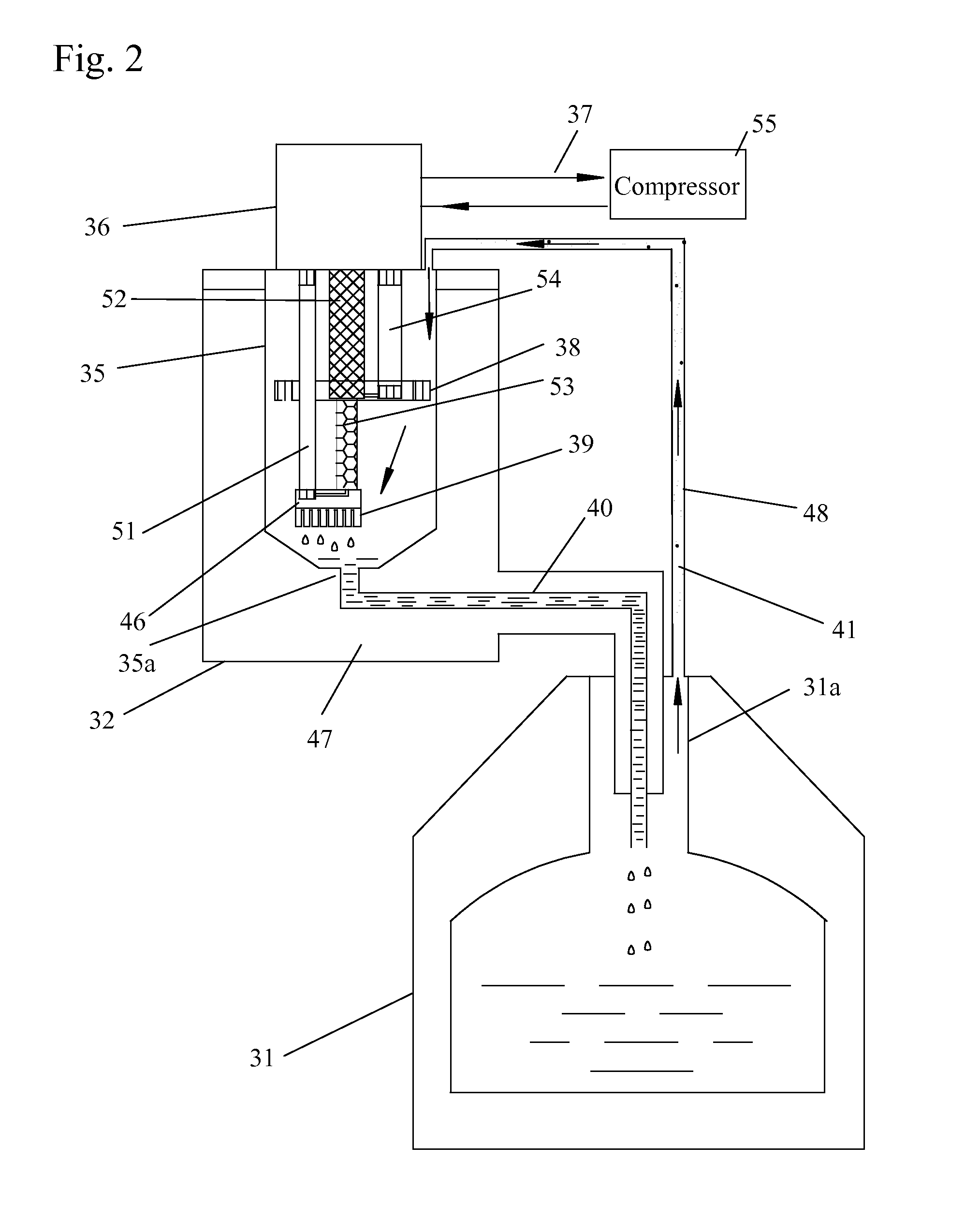
[0016]FIG. 2 shows a reliquifier using a two stage pulse tube cryocooler of the present invention. A portion of the cold head 36 is present within a vacuum insulated sleeve 35 that has an end 35a in fluid communication with a liquid transfer tube 40 leading back to the dewar or cryostat 31. Therefore, the cold head 36 has a hot end outside and a cold end within the vacuum insulated sleeve 35. A vacuum space 47 is present between the vacuum insulated sleeve 65 and the vacuum housing 32.

[0017]The cold head includes a first stage cooling station 38 and a second stage cooling station 46. The first stage cooling station 38 has a temperature which is higher than a temperature of the second stage cooling station 46. The second stage cooling station 46 is mounted to a condenser 39. Heat from the first stage cooling station 38 is removed by the first pulse tube 54 and the first regenerator 52. Heat from the second stage cooling station 46 is removed by the second pulse tube 51 and the second...


PUM


Abstract

A reliquifier using a cryocooler in which an insulated sleeve surrounds a portion of the cold head, a first stage cooling station, and a second stage cooling station, including a condenser. Gas is conveyed from a cryostat to the insulated sleeve, where it is liquefied as it passes over the cold head. An end of the insulated sleeve is connected to a liquid transfer tube for conveying condensed fluid back to the cryostat.

Description

REFERENCE TO RELATED APPLICATIONS[0001]This is a continuation-in-part of co-pending parent patent application Ser. No. 11 / 842 / 420, entitled “Reliquifier”, filed Aug. 21, 2007. The aforementioned application is hereby incorporated herein by reference.FIELD OF THE INVENTION[0002]The invention pertains to the field of gas liquefaction, re-liquefaction and re-condensation with a pulse tube cryocooler. More particularly, the invention pertains to a small scale helium liquifer, reliquifier and recondenser.DESCRIPTION OF RELATED ART[0003]With growing demand for helium worldwide and increased pressure on suppliers resulting in greatly increased prices, it is becoming evident that the world's helium supply is finite and irreplaceable. This invention relates to a small scale helium liquefier or re-liquefier using a pulse tube cryocooler. This invention can help laboratories and industries to recycle helium and produce liquid helium.[0004]Typical closed-cycle regenerative cryogenic refrigerato...

Claims


Application Information

Patent Timeline
IPC IPC(8): F25J1/02F25J5/00
CPCF17C2227/0353F17C2265/034F17C2270/0509F25D19/00F25B9/14F25B2400/17F25B9/10
Inventor WANG, CHAO
Owner CRYOMECH
Why Eureka
Try Eureka