Cryostat configuration with cryocooler and gas gap heat transfer device

a cryostat and heat transfer device technology, applied in the field of cryostat configuration, can solve the problem of not being able to completely prevent the vibration of the cryostat cold head, and achieve the effects of reducing the number of refilling processes, reducing the loss of helium, and reducing the number of helium loss

Inactive Publication Date: 2007-03-08
BRUKER BIOSPIN
View PDF9 Cites 23 Cited by
  • Summary
  • Abstract
  • Description
  • Claims
  • Application Information

AI Technical Summary

Benefits of technology

[0010] In particular, for high-resolution NMR methods, wherein even small vibrations which are introduced e.g. via the cold head of a cryocooler into the system have a negative effect on the spectrum quality, the cryocooler is advantageously a pulse tube cooler, since pulse tube coolers can be operated with extremely low vibration. In principle, other cryocoolers such as e.g. Gifford-McMahon coolers can also be used.
[0011] In a particularly advantageous manner, helium can be liquefied at the coldest stage at a temperature of 4.2 K or less to provide a plurality of different applications in region of very low temperatures. The helium which is evaporated within the cryostat is liquefied at the cold stage which is freely suspended in the neck tube, and drips back into the helium container. This reduces helium loss and the number of refilling processes or permits no-loss operation if the cooling power of the cooler is large enough. The transmission of vibrations from the cold stage to the helium container is also completely eliminated, since the coldest cold stage of the cold head is not connected to the cryostat configuration via a solid bridge.
[0012] In a preferred embodiment of the invention, the tubes of the cold head above the first cold stage and possibly also in the region of further cold stages are surrounded by thermal insulation to eliminate or at least reduce undesired heat input from the neck tube into the tubes of the cold head. The tubes above the first cold stage of the cold head have temperatures between room temperature and the temperature of the first cold stage.

Problems solved by technology

Disadvantageously, the connection between the second cold stage and the helium container generally has a thermal resistance which cannot be neglected, and vibrations of this cold stage may furthermore be transferred to the helium container.
Consequently, a compromise must be found, and it is not possible to completely prevent vibrations of the cryocooler cold head from passing into the cryostat.
This is particularly disadvantageous if it is part of a highly sensitive apparatus such as a magnetic resonance spectrometer, in particular, a magnetic resonance imaging (MRI) apparatus or a nuclear magnetic resonance spectrometer (NMR).

Method used


Image

  • Cryostat configuration with cryocooler and gas gap heat transfer device
  • Cryostat configuration with cryocooler and gas gap heat transfer device
  • Cryostat configuration with cryocooler and gas gap heat transfer device

Examples


Embodiment Construction

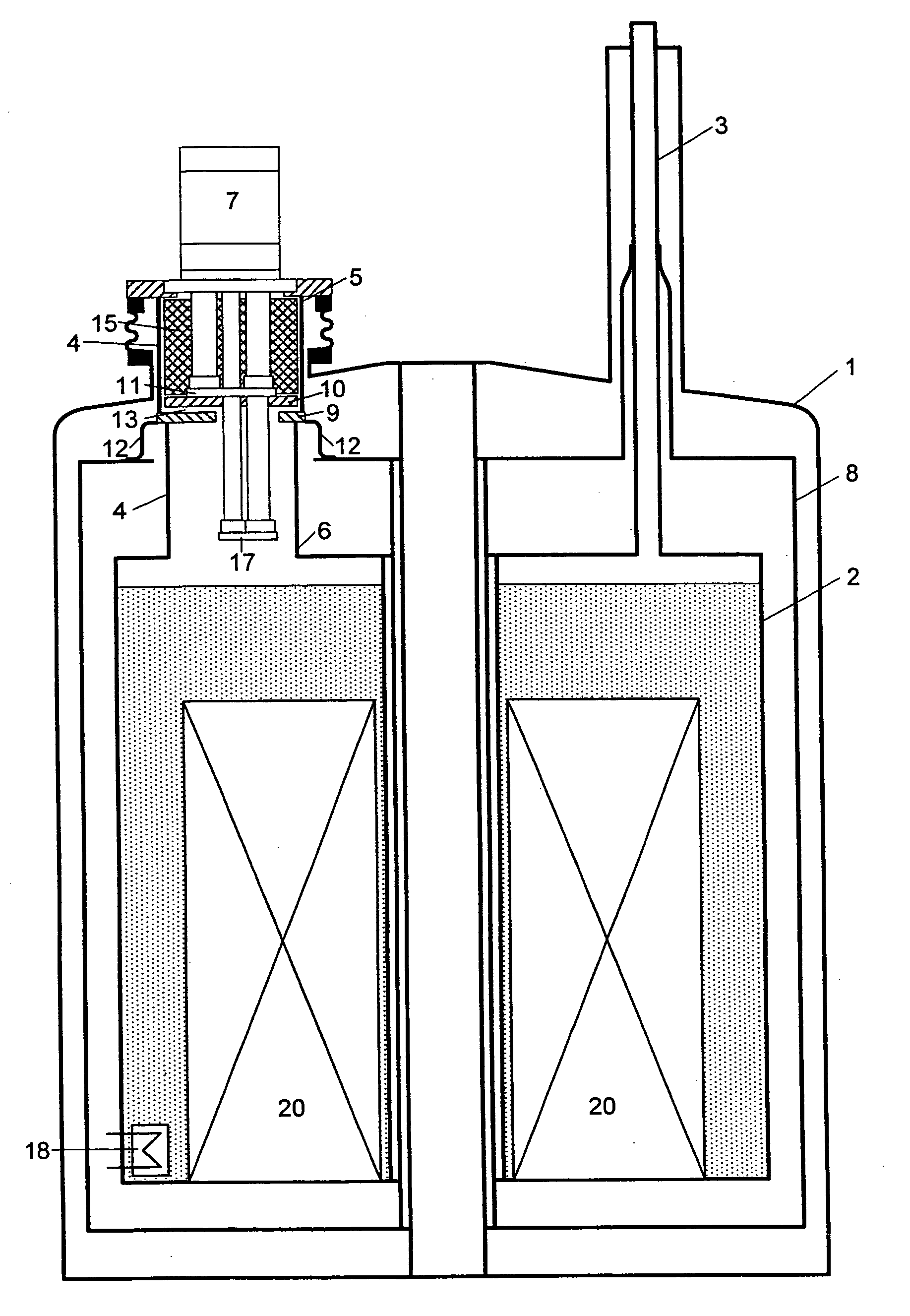
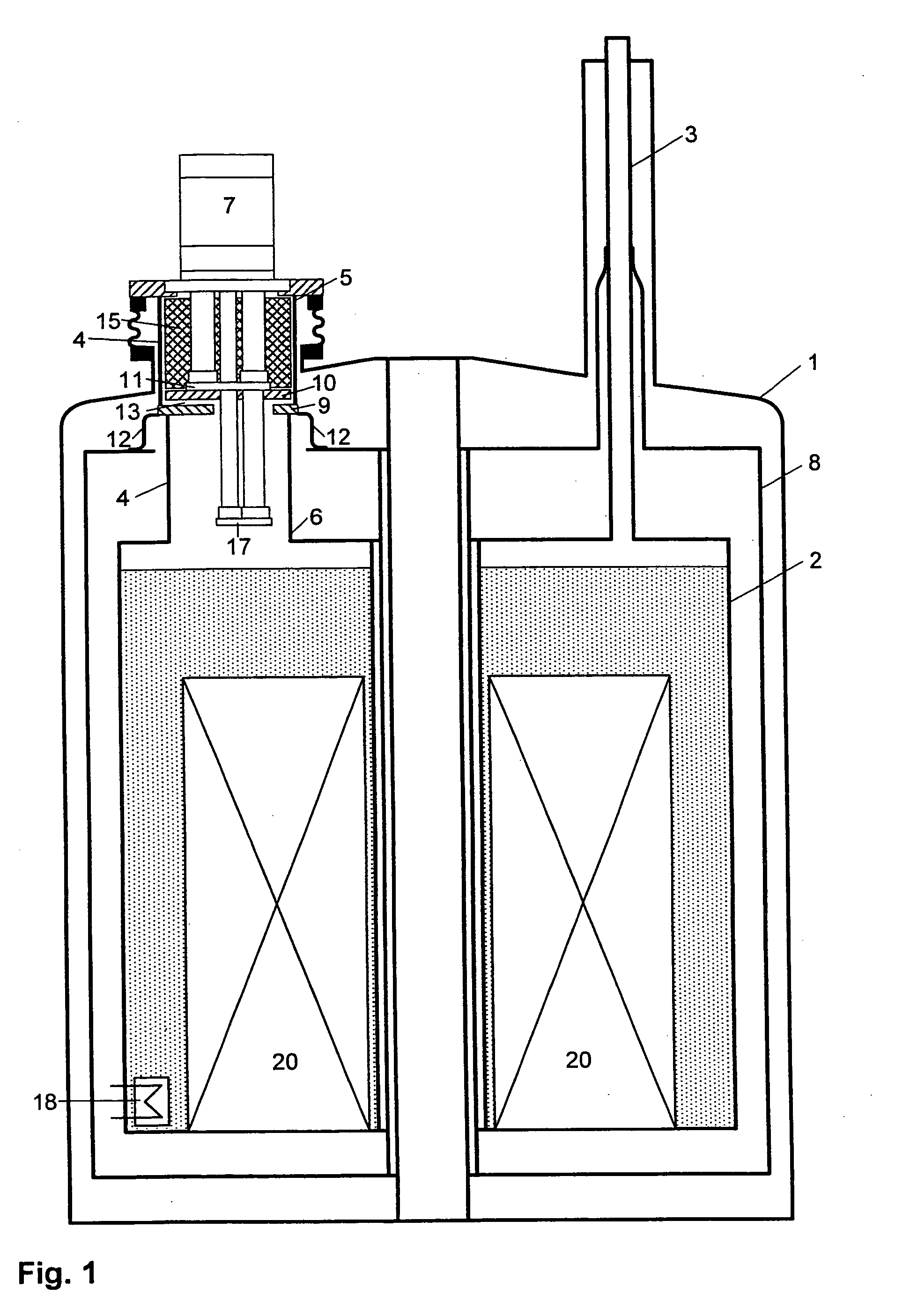
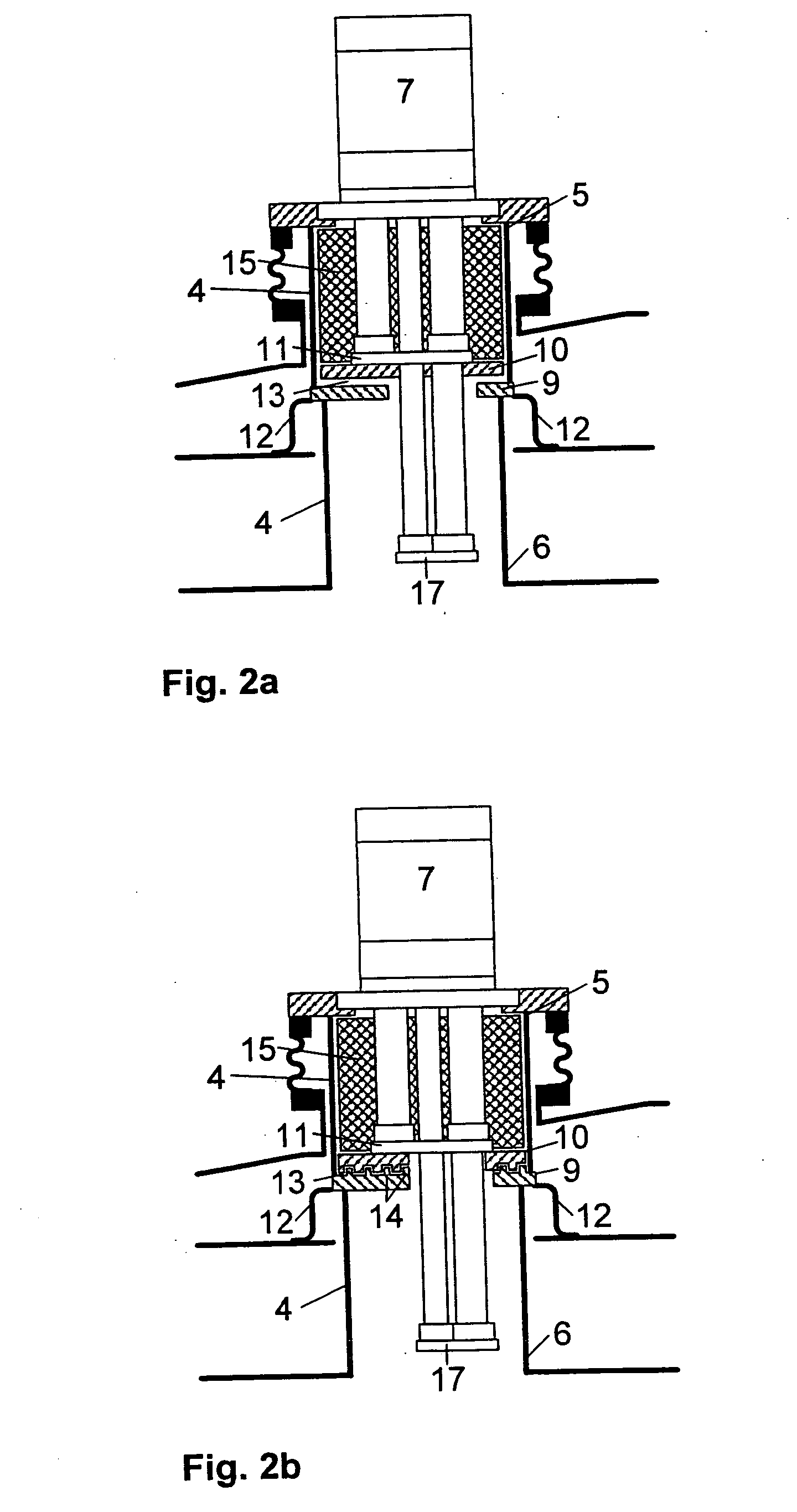
[0027]FIG. 1 shows an embodiment of the inventive cryostat configuration with an outer jacket 1 and a helium container 2 disposed therein. The helium container is connected to the outer jacket 1 via suspension tubes 3. A two-stage cold head 7 of a cryocooler is installed in a neck tube 4 whose upper warm end 5 is connected to the outer jacket 1 and whose lower cold end 6 is connected to the helium container 2. The helium container 2 is surrounded by a radiation shield 8 which is connected in a heat-conducting manner to the suspension tubes 3 and also to a contact surface 9 on the neck tube 4 of the helium container 2. The cold head 7 is slightly lifted to produce a gas gap 13 between a cold surface 10 on the first cold stage 11 of the cold head 7 and the neck tube 4 contact surface 9 which is connected in a heat-conducting manner to the radiation shield 8 via a fixed thermal bridge 12. Heat is transferred from the radiation shield 8 to the cold stage 11 of the cold head 7 via the na...


PUM


Abstract

A cryostat configuration for keeping liquid helium comprises an outer jacket (1) surrounding a helium container (2) connected at at least two suspension tubes (3) to the outer jacket (1), and with a neck tube (4) whose upper warm end (5) is connected to the outer jacket (1) and whose lower cold end (6) is connected to the helium container (2) and into which a multi-stage cold head of a cryocooler (7) is installed, wherein the outer jacket (1), the helium container (2), the suspension tubes (3) and the neck tube (4) delimit an evacuated space, and the helium container (2) is surrounded by at least one radiation shield (8) which is connected in a heat-conducting fashion to the suspension tubes (3) and also to a contact surface (9) on the neck tube (4) of the helium container (2). The cryostat configuration is characterized by a gas gap (13) between one or more cold stages of the cold head (7) and one or more contact surfaces (9) in the neck tube (4) which are each connected in a heat-conducting manner to a radiation shield (8) via a fixed, rigid or flexible thermal bridge (12), heat being transferred through the gas gap (13) from the respective radiation shield (8) to the corresponding cold stage of the cold head (7). A cryostat configuration of this type ensures that no vibrations of the cold head (7) stages pass detectably into the cryostat configuration, wherein the quality of the thermal connection between the cold head (7) and the radiation shield(s) (8) is nevertheless sufficient.

Description

[0001] This application claims Paris Convention priority of DE 10 2004 034 729.8 filed Jul. 17, 2004 the complete disclosure of which is hereby incorporated by reference. BACKGROUND OF THE INVENTION [0002] The invention concerns a cryostat configuration for keeping liquid helium, comprising an outer jacket and a helium container installed therein, wherein the helium container is connected to the outer jacket via at least two suspension tubes, and with a neck tube whose upper warm end is connected to the outer jacket and whose lower cold end is connected to the helium container, as well as a multi-stage cold head of a cryocooler, wherein the outer jacket, the helium container, the suspension tubes and the neck tube delimit an evacuated space, and wherein the helium container is surrounded by at least one radiation shield which is connected in a thermally conducting fashion to the suspension tubes and to a contact surface on the neck tube of the helium container. [0003] One possibilit...

Claims


Application Information

Patent Timeline
Patent Type & Authority Applications(United States)
IPC IPC(8): F25B9/00F25B19/00
CPCF25B9/10F25B9/145F25D19/006F25B2400/17F25B2309/1408
Inventor KRAUS, ANDREASMRAZ, BEATBOESEL, JOHANNES
Owner BRUKER BIOSPIN
Why Eureka
Try Eureka