Control method for pulse tube cryocooler

a control method and technology of cryocooler, applied in gas cycle refrigeration machines, refrigeration machines, refrigeration safety arrangements, etc., can solve the problems of reducing the acoustic power that the pulse wave generator is able to generate, reducing the cooling capacity, and reducing the efficiency of electric to acoustic energy conversion of pulse wave generators, so as to achieve less power, improve refrigeration efficiency, and improve cooling power output

Inactive Publication Date: 2008-03-27
PRAXAIR TECH INC
View PDF12 Cites 22 Cited by
  • Summary
  • Abstract
  • Description
  • Claims
  • Application Information

AI Technical Summary

Benefits of technology

[0013]In such manner, whether the refrigeration load temperature and input power to the cryocooler are at the design condition for the pulse tube cryocooler or not, as the refrigeration load varies and therefore the sensed temperature, not only will the power input of the acoustic source of the cryocooler be varied but also impedance of the inertance network. As a result, less power will be required

Problems solved by technology

If the pulse wave generator to coldhead and inertance network matching is poor, the pulse wave generator's electric to acoustic energy conversion efficiency will be diminished and the acoustic power that the pulse wave generator is able to generate is therefore reduced.
Less acoustic power delivered to the coldhead typically translates into less heat being pumped by the cryocooler and lower cooling capacity.
This will result in either an increas

Method used


Image

  • Control method for pulse tube cryocooler
  • Control method for pulse tube cryocooler
  • Control method for pulse tube cryocooler

Examples


Embodiment Construction

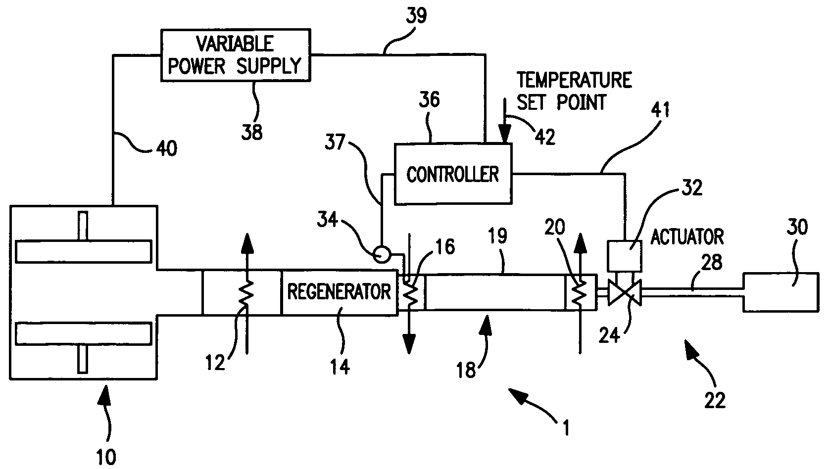
[0026]With reference to FIG. 1, a pulse tube cryocooler 1 is illustrated that is controlled in accordance with the present invention. Pulse tube cryocooler 1 is provided with an acoustic source in the form of a pulse wave generator 10 that can utilize a linear motor to generate pulsations within a gas contained within pulse tube generator 1. Such gas can be for example, neon or helium. Located within the coldhead 18 is an after cooler 12 a regenerator 14, a cold heat exchanger 16, a thermal buffer tube 19 and a warm heat exchanger 20.

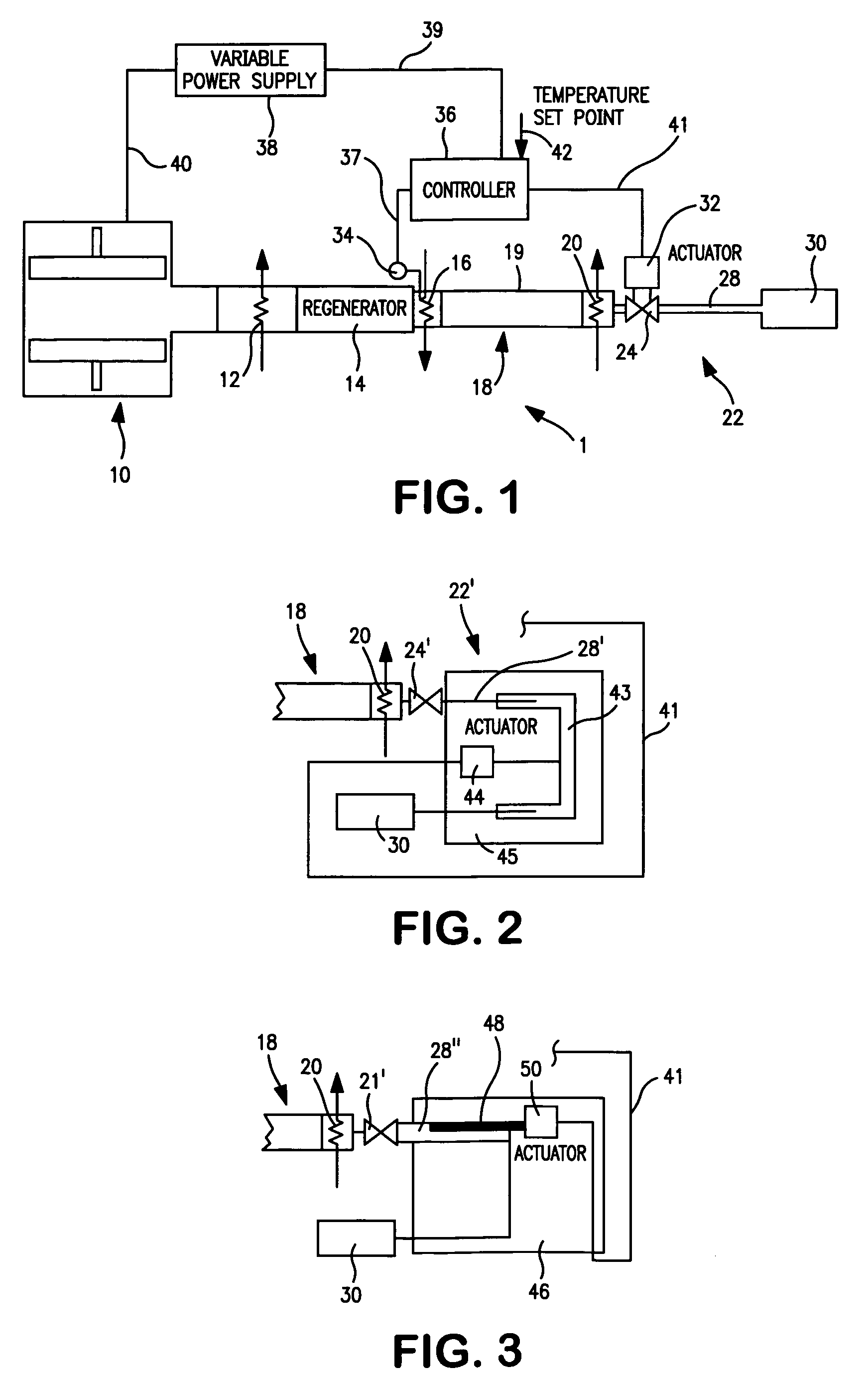
[0027]The tuning of the pulse tube cryocooler is accomplished with an inertance network 22 that is provided with a variable flow restrictor 24, an inertance tube 28 and a compliance vessel 30.

[0028]During operation, the acoustic source 10 generates an acoustic wave that is propagated within coldhead 18. As the wave traverses coldhead 18, the heat of compression, acoustic energy dissipated in the regenerator 14 and heat pumped by the action of the acoust...


PUM


Abstract

Method of controlling a pulse tube cryocooler in which the power input to the acoustic source is varied to maintain temperature of a refrigeration load or a temperature that is at least referable to the temperature of the refrigeration load, at a set point temperature. Additionally, the impedance of an inertance network of the pulse tube cryocooler is also adjusted to obtain a maximum cooling power to the refrigeration load at the particular temperature as sensed and the particular power that is being supplied to the acoustic source.

Description

FIELD OF THE INVENTION [0001]The present invention relates to a method of controlling a pulse tube cryocooler to maintain a refrigeration load at a set point temperature in which the power input to an acoustic source of the pulse tube cryocooler is controlled to maintain the set point temperature and the impedance of an inertance network of the pulse tube cryocooler is adjusted to obtain a maximum cooling power to the refrigeration load at the refrigeration load temperature.BACKGROUND OF THE INVENTION [0002]Pulse tube cryocoolers consist of a pulse wave generator, which converts electrical energy to acoustic energy, a coldhead which utilizes the acoustic energy to pump heat from a refrigeration load to a warmer heat sink and an inertance network for generating proper phase angle between gas flow and pressure oscillation within the coldhead.[0003]Typically, a non-linear motor is used as the acoustic source and is referred to as a pulse wave generator. The pulse wave generator, coldhe...

Claims


Application Information

Patent Timeline
IPC IPC(8): F25B9/00F25B49/00
CPCF25B9/145F25B2309/1407F25B2309/1408F25B2309/1427F25B2309/1423F25B2309/1424F25B2309/1411
Inventor RAMPERSAD, BRYCE MARK
Owner PRAXAIR TECH INC
Why Eureka
Try Eureka