Display Device

a display device and display housing technology, applied in the field of display devices, can solve the problems of affecting the appearance of the display device, the structure of the display device becomes complicated, and the wall-mounting display device is undesirable, so as to achieve the effect of reducing the structure and removing the device detachabl

Inactive Publication Date: 2009-02-26
MEITAKU IND
View PDF18 Cites 40 Cited by
  • Summary
  • Abstract
  • Description
  • Claims
  • Application Information

AI Technical Summary

Benefits of technology

[0012]In yet another embodiment, the front cover panel is inserted in a gap between the frame on both ends of the display body and the optical diffusion case. Preferably, the front cover panel is inserted between the back surface of the frame member and an illumination surface of the optical diffusion case and is detachable between said frame members vertically or horizontally. Advantageously, the detachable front cover allows the positive print film to be changed quickly and easily.
[0021]In addition to the above-mentioned features, embodiments of the invention can include the front cover panel inserted in the gap between the frame at the ends of the display body and the optical diffusion case and can be removed detachably. This structure allows the positive print film to be exchanged quickly and easily.

Problems solved by technology

However, the housing for the fluorescent lamp is relatively thick and the use of multiple light guiding panels leads to further thickening the housing.
As a result, the structure thereof becomes complicated.
Moreover, this type of display device is suitable for a stand-alone type display device but it is undesirable for wall-mounting display devices because the housing protrudes from the front / rear side.

Method used


Image

  • Display Device
  • Display Device
  • Display Device

Examples


Embodiment Construction

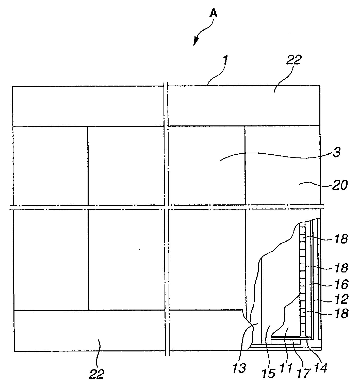
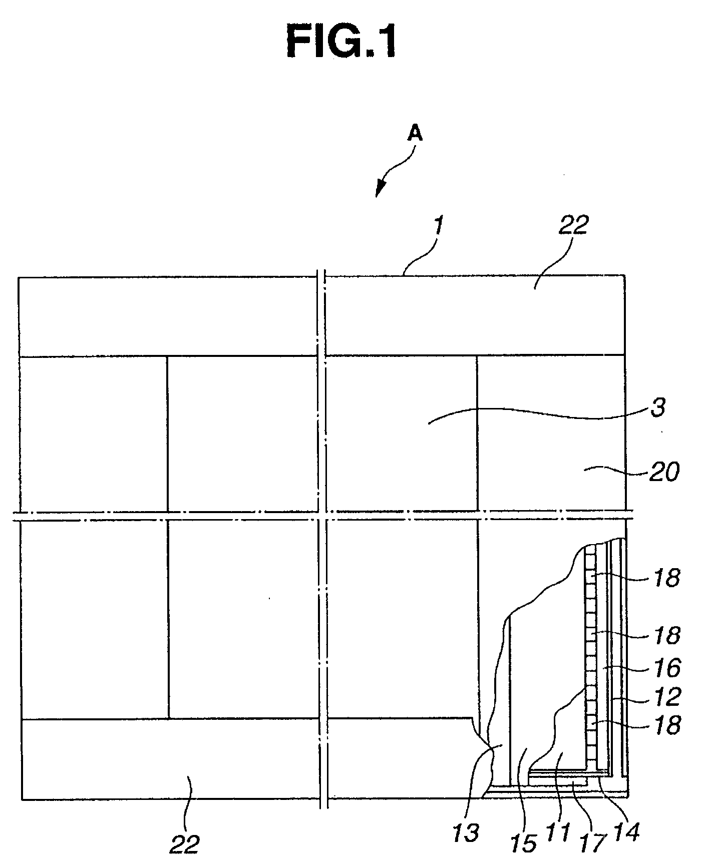
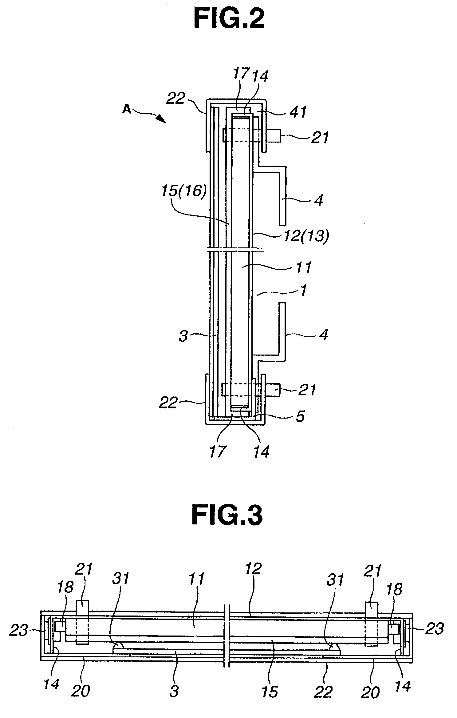
[0033]The present invention will be explained more specifically by referring the examples shown in the attached drawings. Referring to FIGS. 1 to 3, letter (A) represents the display device. The display device A includes a display body 1, frame members 22, and a front cover panel 3. The display body 1 includes a light guiding panel 11 sandwiched between a reflection case 12 and an optical diffusion case 15, which are fitted in each other, and LED light sources 18. The LED light sources 18 are disposed on the flanges of the cases 12 or 15, confronting the light incident end surfaces of the light guiding panel 11. The frame members 22 are attached on one set or both sets of opposed ends of the display body 1.

[0034]The detachable front cover panel 3 covers the illumination surface of the optical diffusion case 15 between the frame members 22. One of the reflection case and the optical diffusion case in the display body 1, or, the reflection case 12, in the present embodiment, is fabric...


PUM


Abstract

A wall-mounted display device, which uses a light guiding panel for an LED light source includes display body 1 with an optical panel 11 housed in a box-like optical diffusion case 15 with flanges 14 formed on the periphery of a substrate 13. A reflection case 12 fits in the optical diffusion case 15, which has a U-shaped cross section and flanges 14 formed on the upper and lower ends of the substrate16. LED light sources 18 are respectively disposed on the right and left flanges 14 of the reflection case 12 to supply incident light into the light guiding panel 11. Frame members 22, each having a U-shaped cross section, fit in the upper and lower ends of the display body 1, respectively. Each U-shaped frame member is securely fixed with a screw 21 inserted through the rear surface of the frame member, in such a way that the screw 21 is not exposed from the front side of the display body. Frame members 20, each having an L-shaped cross section, are respectively fixed on the right and left ends of the display body 1, with a magnet 23. A transparent cover panel 3 is disposed detachably between the frame member 20 and the optical diffusion case 15. Brackets 4 are fastened on the U-shaped frame members with screws 21 to allow wall mounting.

Description

CROSS REFERENCES TO RELATED APPLICATIONS[0001]Not Applicable.STATEMENT REGARDING FEDERALLY SPONSORED RESEARCH[0002]Not Applicable.BACKGROUND OF THE INVENTION[0003]The present invention relates to a display device in which a positive image film is back illuminated, such as a display panel including a light guiding plate at the forefront thereof. This display device includes a light source unit housing a fluorescent light source in a closed space of a housing, a large number of light guiding panels disposed over the upper surface of said light source unit, and a reflection panel disposed on the back surfaces of the light guiding panels. The light of the fluorescent light source is transmitted from the light incident end surface to the light guiding panel. Due to light guidance according to the light guiding pattern formed on the light guiding panel, a positive print film, disposed on the front surface, is back-illuminated as uniformly as possible and with high brightness. One such dis...

Claims


Application Information

Patent Timeline
Patent Type & Authority Applications(United States)
IPC IPC(8): F21V17/00F21V8/00
CPCG02B6/0051G02B6/0073G09F13/22G09F13/0413G09F13/18G02B6/0088G02F1/1333G02F1/1335G09F9/00
Inventor MATSUI, HIROKAZUMURASE, SHINZO
Owner MEITAKU IND
Why Eureka
Try Eureka