Transmitter and transmitter/receiver
- Summary
- Abstract
- Description
- Claims
- Application Information
AI Technical Summary
Benefits of technology
Problems solved by technology
Method used
Image
Examples
first embodiment
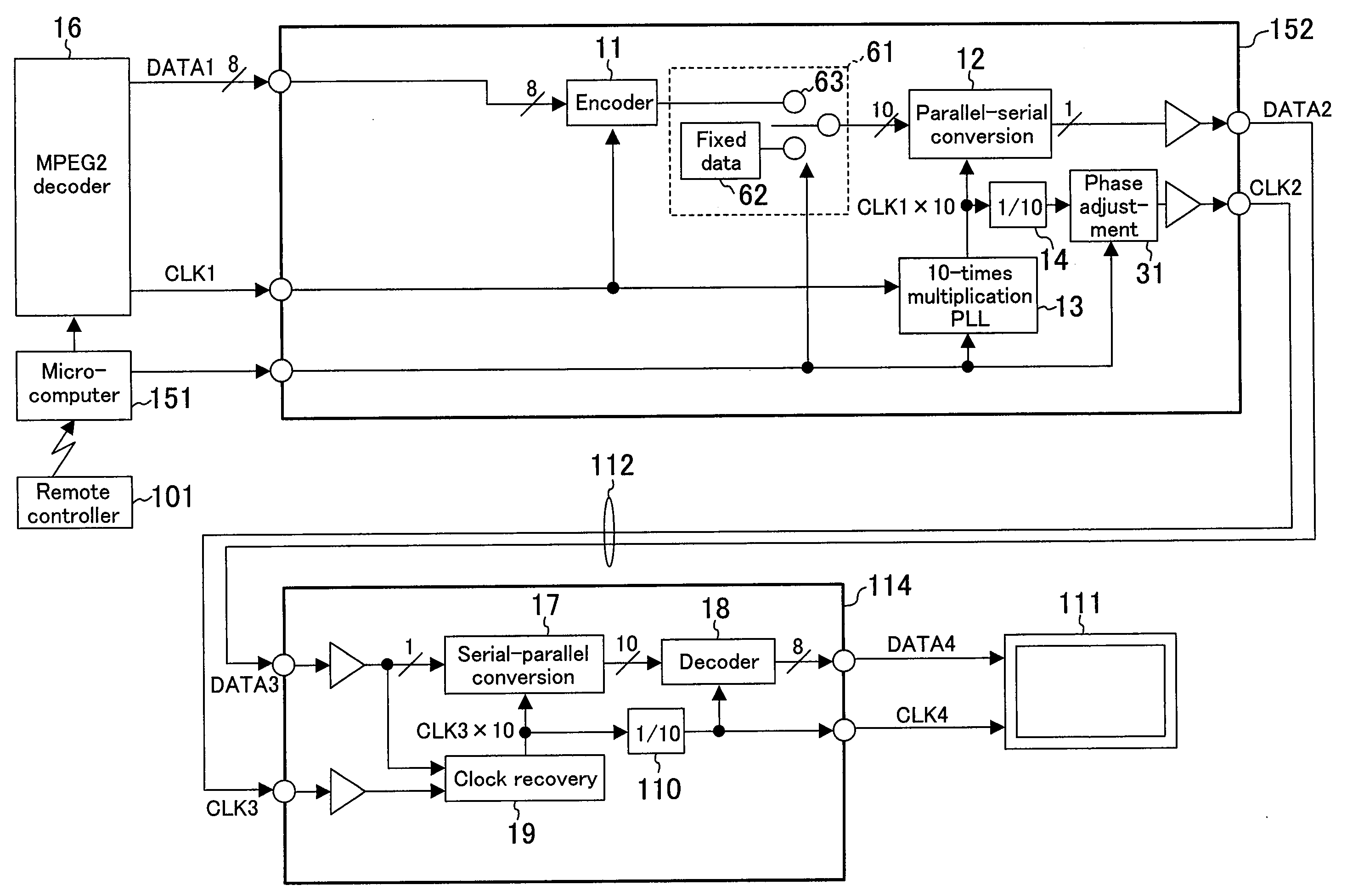
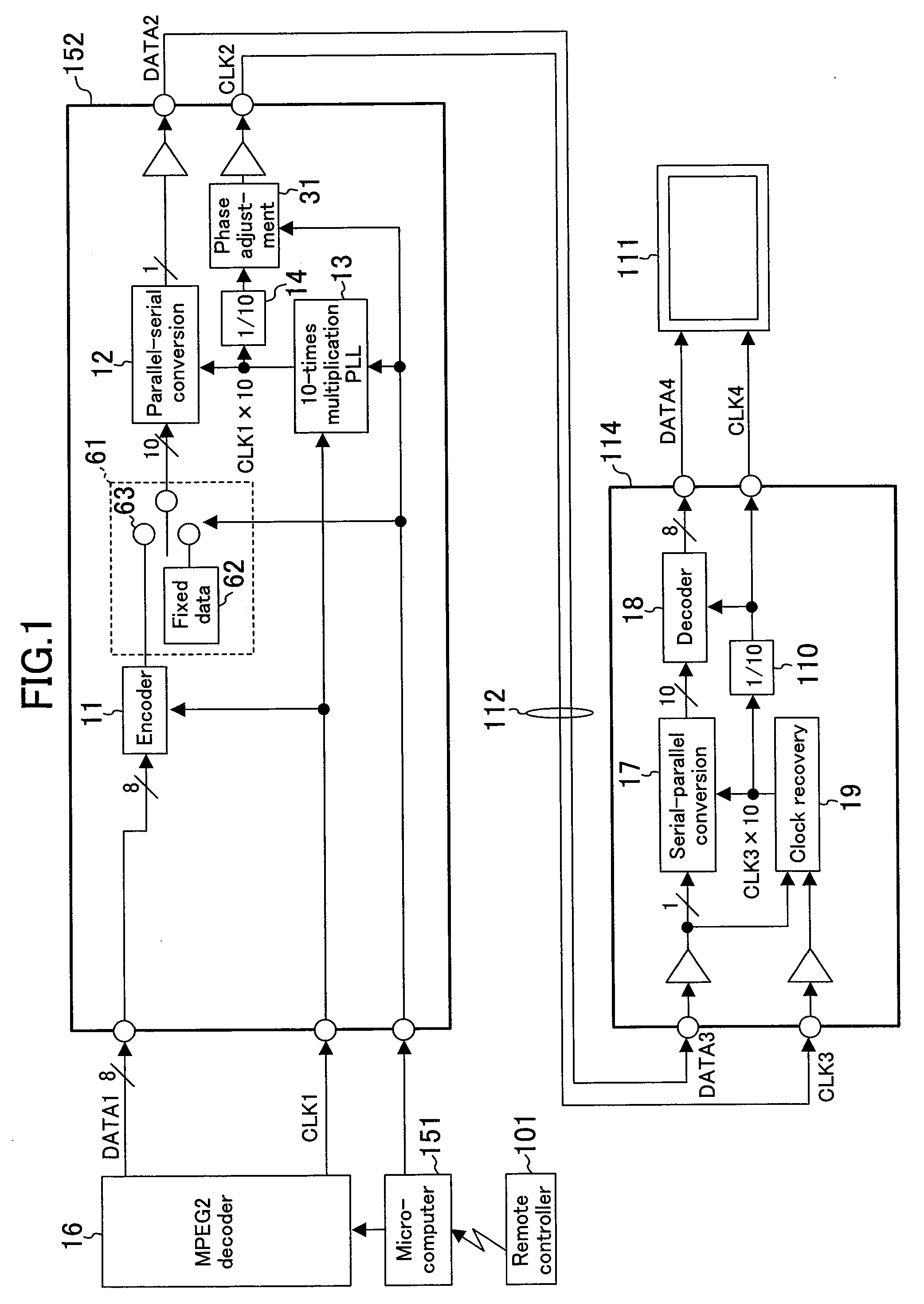
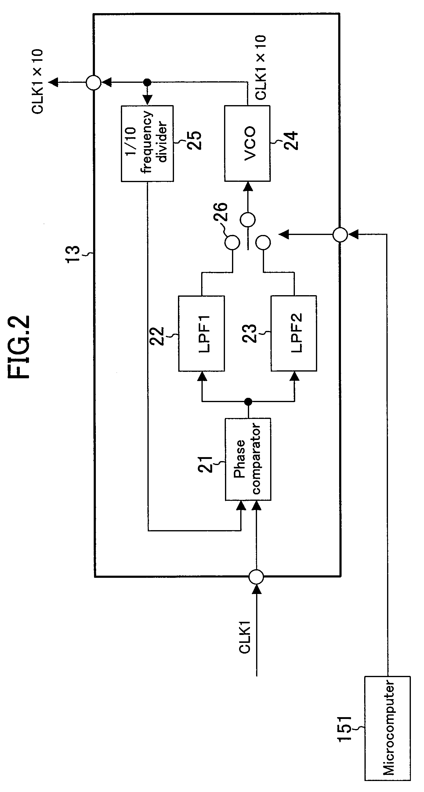
[0076]FIG. 1 is a block diagram showing a configuration including a transmitter according to a first embodiment of the present invention. In FIG. 1, like elements to those of FIG. 8 described above in the background art section are denoted by like reference numerals to those in FIG. 8, and will not be further described below. A transmitter 152 includes, instead of the 10-times multiplication PLL 32, a 10-times multiplication PLL 13 capable of producing a multiplied clock CLK1×10 having a frequency that is N times that of an input clock CLK1 (N is a natural number; herein N=10) and increasing / decreasing the amount of jitter of the multiplied clock CLK1×10. Moreover, the transmitter 152 includes a phase adjustment section 31 capable of increasing / decreasing the amount of phase shift, i.e., the amount of jitter, of the transmit clock produced by the frequency divider 14, and a fixed data producing section 61 capable of setting the output of the encoder 11 to be fixed data. A microcompu...
second embodiment
[0104]FIG. 5 is a block diagram showing a configuration including a transmitter according to a second embodiment of the present invention. In FIG. 5, like elements to those of FIG. 1 and those of FIG. 8 described above in the background art section are denoted by like reference numerals to those in FIGS. 1 and 8, and will not be further described below. The transmitter 162 does not include the fixed data producing section 61, but instead includes a mute signal producing section 71 capable of setting the input to the encoder 11 to a mute signal as predetermined fixed data. A microcomputer 161 as a control section controls the 10-times multiplication PLL 13, the phase adjustment section 31 and the mute signal producing section 71. The microcomputer 161 operates based on information from the remote controller 101. The mute signal producing section 71, the encoder 11 and the parallel-serial conversion section 12 together form a transmit data producing section.
[0105]The mute signal produ...
third embodiment
[0120]FIG. 6 is a block diagram showing a configuration including a transmitter according to a third embodiment of the present invention. In FIG. 6, like elements to those of FIG. 1 and those of FIG. 8 described above in the background art section are denoted by like reference numerals to those in FIGS. 1 and 8, and will not be further described below.
[0121]The operation of the configuration of FIG. 6 is basically the same as that of the configuration of FIG. 1. Specifically, a microcomputer 221 as a control section controls the 10-times multiplication PLL 13, the phase adjustment section 31 and the fixed data producing section 61, as in the first embodiment. What is different from the first embodiment is that the microcomputer 221 operates based on information read out from EDID 171, instead of information from the remote controller 101.
[0122]The EDID 171 stores various information on the receiver 114 or the TV 111. For example, the various information recorded include the resoluti...
PUM
 Abstract
Description
Claims
Application Information
 - R&D
- Intellectual Property
- Life Sciences
- Materials
- Tech Scout
- Unparalleled Data Quality
- Higher Quality Content
- 60% Fewer Hallucinations
Browse by: Latest US Patents, China's latest patents, Technical Efficacy Thesaurus, Application Domain, Technology Topic, Popular Technical Reports.
© 2025 PatSnap. All rights reserved.Legal|Privacy policy|Modern Slavery Act Transparency Statement|Sitemap|About US| Contact US: help@patsnap.com


