Portable drill pipe handling apparatus for use with oil and gas well drilling rigs

a technology for drilling rigs and handling equipment, applied in drilling pipes, drilling rods, drilling casings, etc., can solve the problems of occupying more space and typically stacked pipes

Inactive Publication Date: 2009-02-26
MALTBY SCOTT R
View PDF21 Cites 72 Cited by
  • Summary
  • Abstract
  • Description
  • Claims
  • Application Information

AI Technical Summary

Problems solved by technology

Many drillers face the problem of transferring drill pipe from the pipe rack to the elevated rig deck.
One of the problems with the transportation of drill pipe is that of maintaining a proper orientation of the section of the drill pipe relative to the rig floor, especially when it is about to be either removed from the pipe transportation unit to the rig floor or transferred from the rig floor back to the pipe transportation unit.
Another problem with the transportation of pipe racks to the drill floor is that the pipe is typically stacked in layers.
The truck mounted units are more diversified and portable, but take up more space because of the typically large truck portion of the apparatus.

Method used


Image

  • Portable drill pipe handling apparatus for use with oil and gas well drilling rigs
  • Portable drill pipe handling apparatus for use with oil and gas well drilling rigs
  • Portable drill pipe handling apparatus for use with oil and gas well drilling rigs

Examples


Embodiment Construction

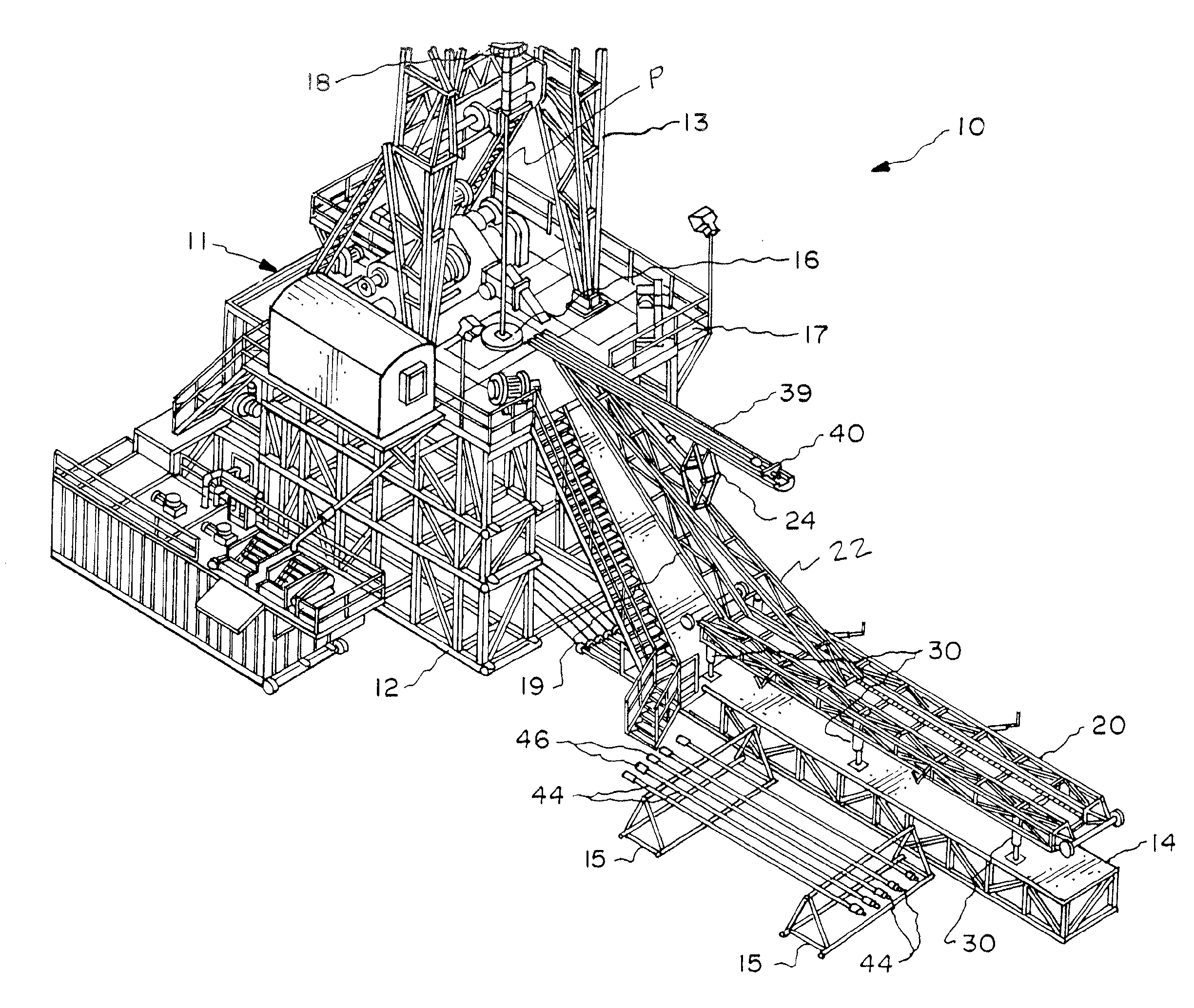
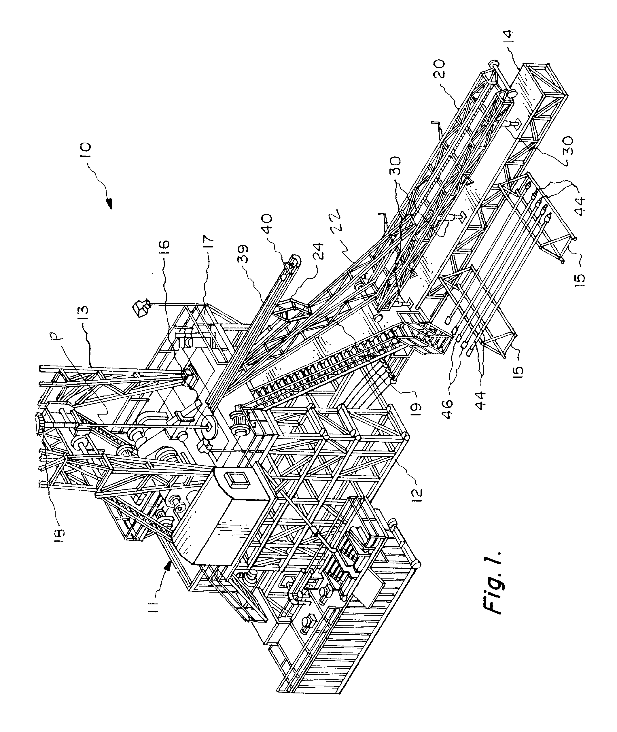
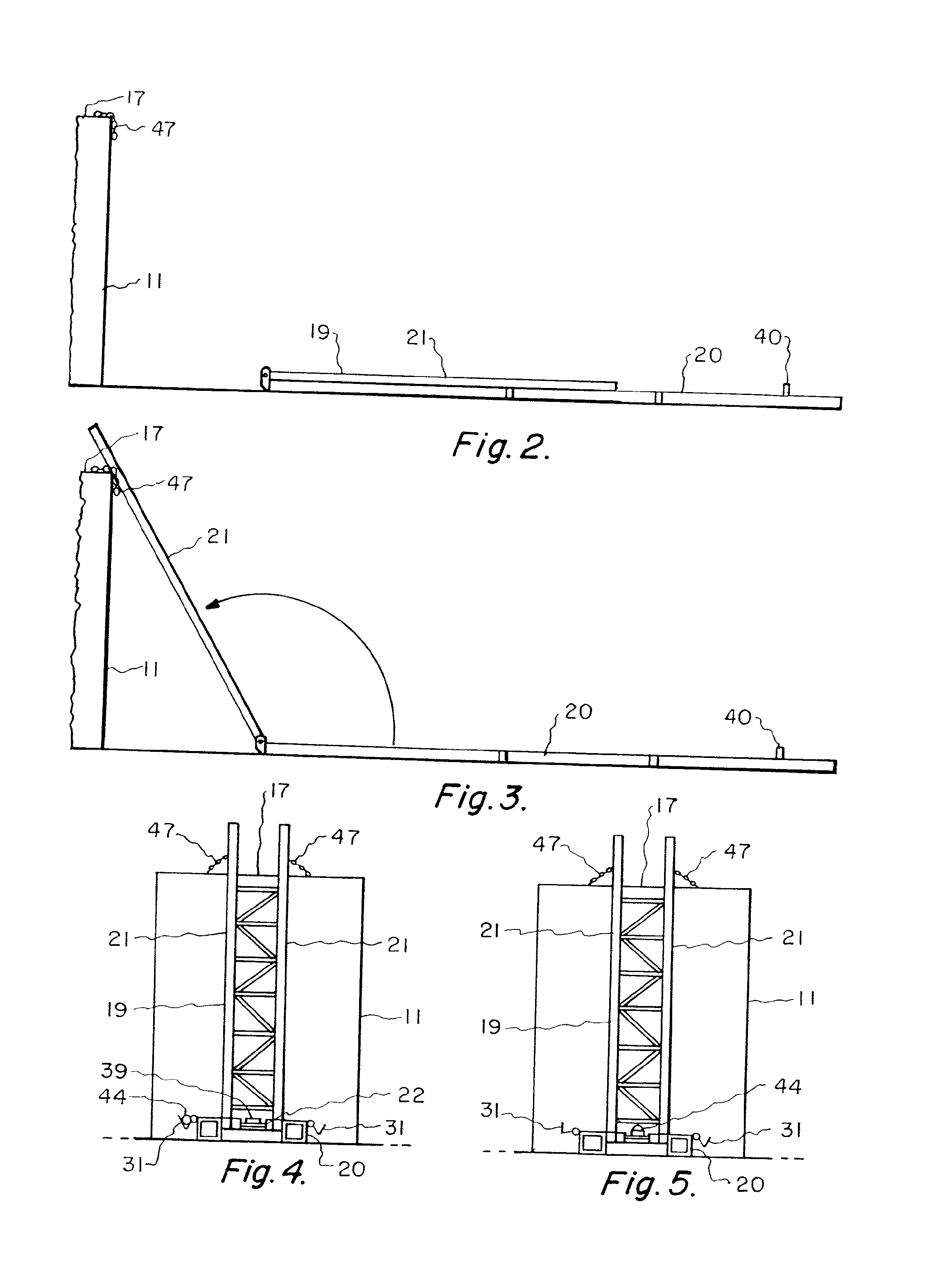
[0048]FIGS. 1-20 show the preferred embodiment of the apparatus of the present invention, designated generally by the numeral 10 in FIG. 1. Drill pipe transfer apparatus or “pipe skate: 10 is used with drilling rig 11, enabling the transfer of successive lengths or joints 44 of drill pipe that are stacked and stored in a generally horizontal position on a pipe rack 15, to an elevated deck or floor 17 of an oil and gas well drilling rig 11 having a base 12 (see FIG. 1).

[0049]The apparatus 10 of the present invention provides an optionally portable pipe skate for the safe transportation of the pipe joint members 44 from a horizontal position on pipe rack 15 and then diagonally to the drilling rig floor 17 and / or to a pipe elevator for vertical positioning (see pipe string P, FIG. 1) before transport into the well bore.

[0050]The apparatus 10 of the present invention includes a main frame 20 that can be positioned on the top of a drill rig catwalk 14. The apparatus 10 includes folding s...


PUM


Abstract

A pipe handling apparatus transfers successive lengths of drill pipe that are stored in a generally horizontal position on a pipe rack, to an elevated position on the rig deck of an oil and gas well drill rig. An elongated frame includes a base section with a folding section that can be inclined. Both the base and folding sections provide toothed racks. A trestle section travels from the base section toward the inclined section. Pinion gears at opposed end portions of the trestle section engage the toothed racks of the base and folding sections. The trestle section gradually increases in inclination as its front end portion travels toward and up hoisting rails of the inclined folding section. While the rear end of the trestle section remains on the base section, the front end portion of the trestle section climbs the toothed racks of the inclined rails.

Description

CROSS-REFERENCE TO RELATED APPLICATIONS[0001]Priority of U.S. Provisional Patent Application Ser. No. 60 / 956,815, filed 20 Aug. 2007, incorporated herein by reference, is hereby claimed.STATEMENT REGARDING FEDERALLY SPONSORED RESEARCH OR DEVELOPMENT[0002]Not applicableREFERENCE TO A “MICROFICHE APPENDIX”[0003]Not applicableBACKGROUND OF THE INVENTION[0004]1. Field of the Invention[0005]The present invention relates to oil and gas well drilling and to an apparatus for handling pipe that is used during oil and gas well drilling (including geothermal and / or mineral drilling). More particularly, the present invention relates to an improved pipe handling apparatus for transferring successive lengths of drill pipe from a pipe rack to the deck of a drilling rig, wherein a moving section of the apparatus lifts pipe upwardly along an inclined path with a trestle that is driven to travel upon a base or supporting frame, the trestle gradually increasing in inclination as it moves between a low...

Claims


Application Information

Patent Timeline
Patent Type & Authority Applications(United States)
IPC IPC(8): E21B19/15
CPCE21B19/15
Inventor MALTBY, SCOTT R.
Owner MALTBY SCOTT R
Why Eureka
Try Eureka