
Nasal Device

a technology for nasal devices and nasal members, applied in the field of nasal devices, can solve the problems of reducing effectiveness, falling out or repositioning of current nasal devices, and reducing so as to prevent accidental dislodgement of nasal members and minimize the risk of nasal tissue damage

Inactive Publication Date: 2009-02-26
BENSON MEDICAL SERVICES
View PDF15 Cites 23 Cited by
  • Summary
  • Abstract
  • Description
  • Claims
  • Application Information

AI Technical Summary

Benefits of technology

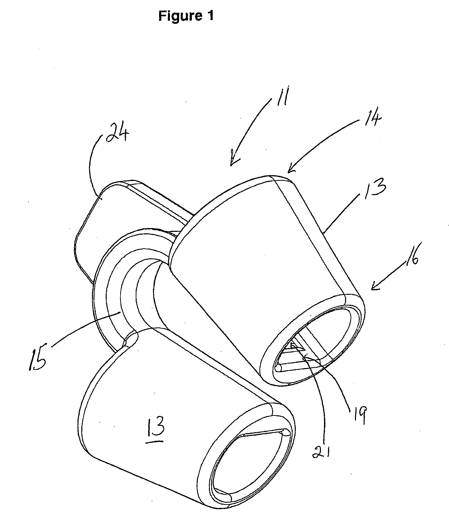
[0008]The nasal member may be any suitable shape which in use is able to form an air passageway within the nasal cavity. Preferably each of the nasal members is hollow and substantially tubular in shape. Each of the nasal members preferably has an internal bore extending the length of the member. Preferably each of the nasal members has a truncated conical shape where the diameter across one end is smaller than the diameter across the opposite end. Preferably each of the nasal members has a truncated conical shape wherein there is a bore extending the length of the member. The narrower end of the nasal member is preferably positioned further within the nasal cavity than the larger end when the dilator member is inserted within the nose. Preferably the narrower end of the nasal member has a rounded edge to reduce the risk of damage to nasal tissue.
[0013]The dilator member preferably is made of soft material. The dilator member is preferably made of soft, resiliently deformable material. The dilator member preferably is made of plastics. The dilator member is preferably made of non-toxic, non-abrasive, soft medical plastics to minimize the risk of damage to nasal tissue.
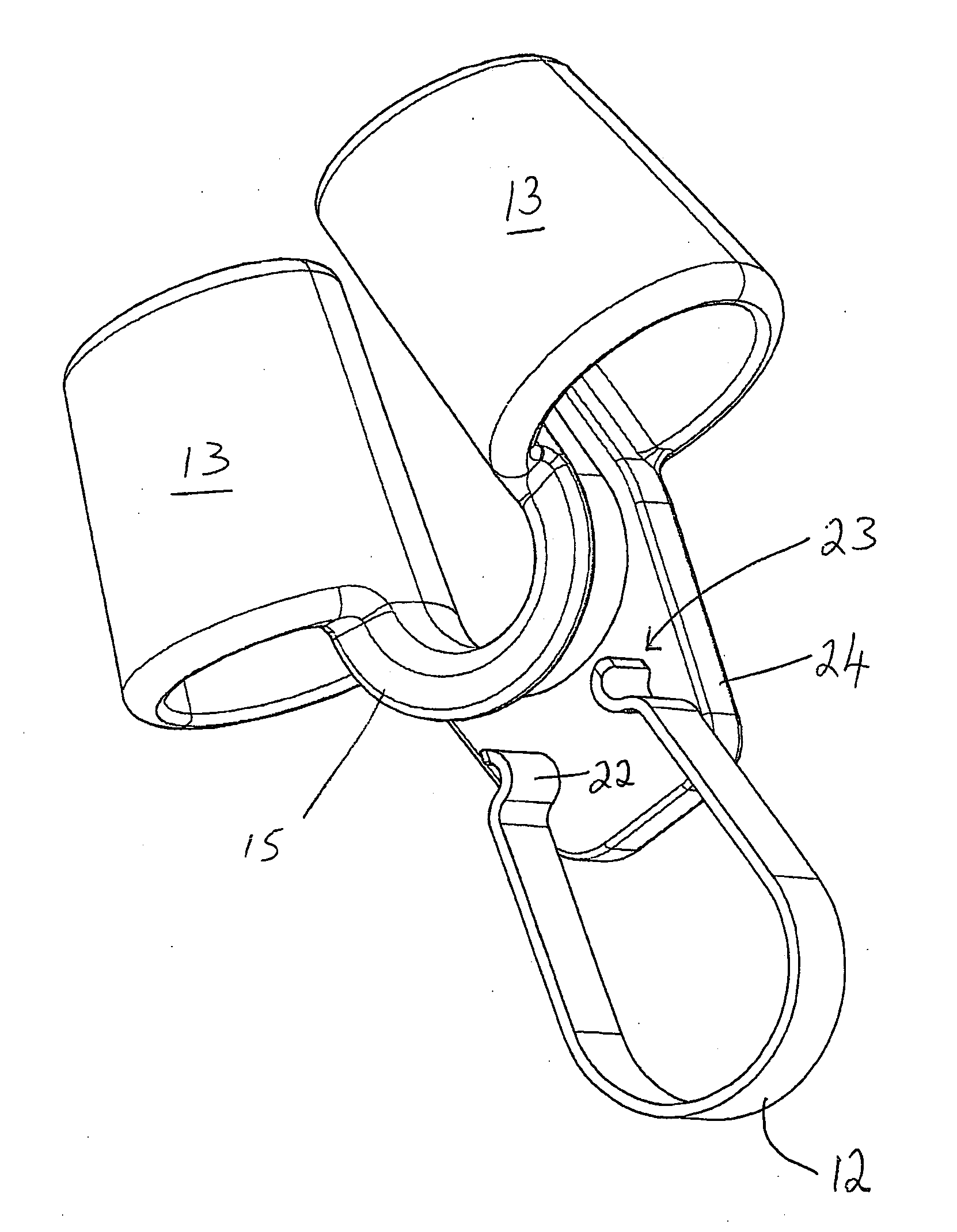
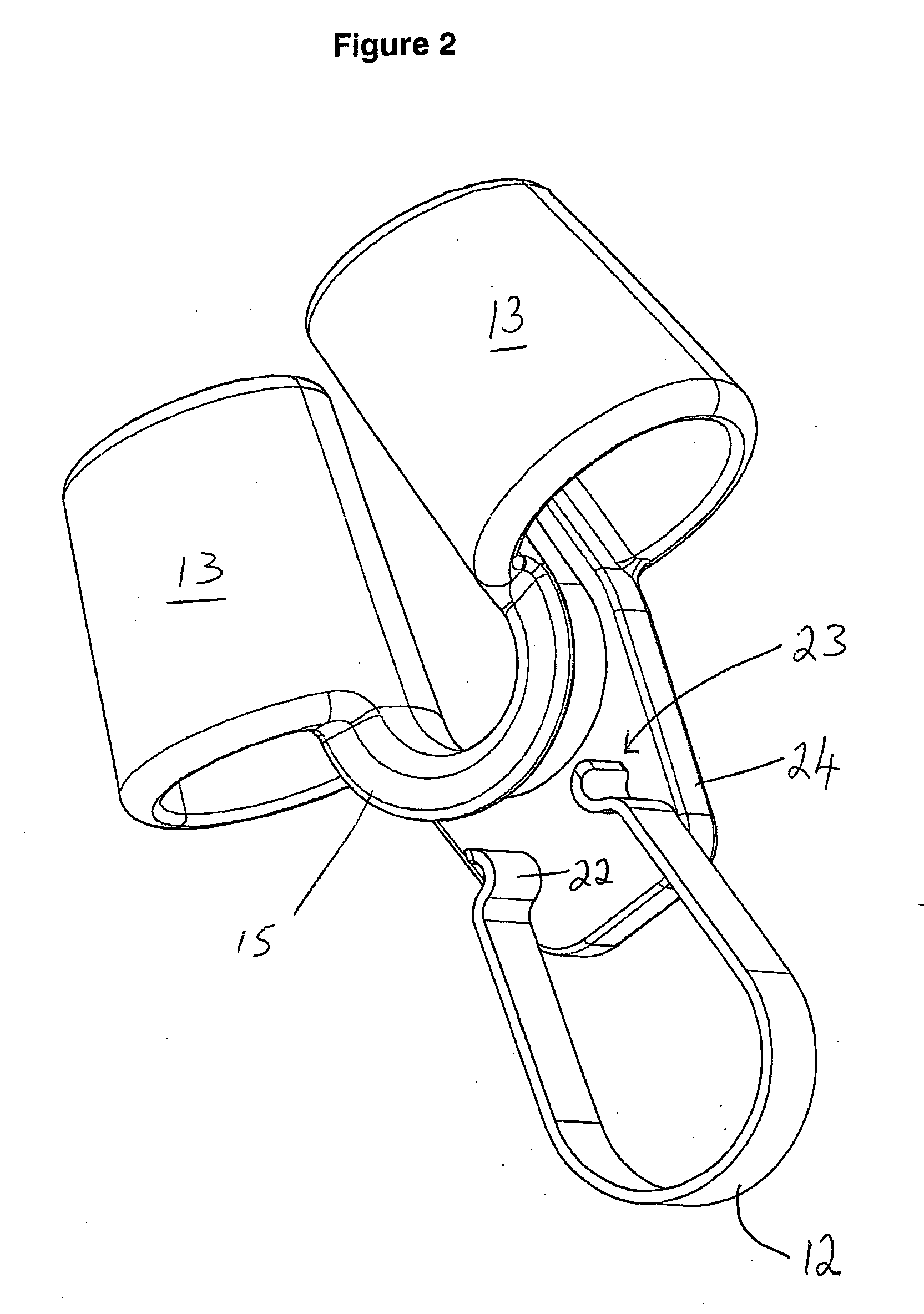
[0014]The spring biased clip is preferably substantially U-shaped. The spring biased clip preferably has locating protrusions on opposing clip ends. The locating protrusions preferably oppose each other. The locating protrusions assist in positioning the clip by locating within the respective locating recess in each nasal member. When the spring biased clip is located within each nasal member, the clip preferably abuts each nasal member substantially against the nasal septum wall. When in position the clip preferably prevents accidental dislodgement of the nasal members in the nasal cavities and movement of the nasal members by airflow with inhalation and expiration.
[0019]Preferably each of the nasal members has a substantially truncated conical shape where the diameter across one end is smaller than the diameter across the opposite end. Preferably each of the nasal members has a substantially truncated conical shape wherein there is a bore extending the length of the member. Preferably the narrower end of the nasal member has a rounded edge to reduce the risk of damage to nasal tissue.

Problems solved by technology

The disclosed nasal devices however can become accidentally dislodged and fall out or repositioned with reduced effectiveness.
Furthermore where the nose or nasal septum have a different size or shape or a person has a deviated septum, current nasal devices may not fit or comparatively be more easily dislodged.

Method used


Image

  • Nasal Device
  • Nasal Device
  • Nasal Device

Examples


Embodiment Construction

[0027]With reference to the figures there is shown a nasal device 10 including a dilator member 11 and spring biased clip 12. The dilator member 11 has two hollow tubular nasal members 13. Each nasal member 13 decreases in diameter to form an elongate truncated cone. The larger end 14 of each nasal member 13 is joined by a bridging portion 15 which maintains the nasal members 13 in a similar orientation and in spaced relationship with each other. The bridging portion 15 has a tab 17 allowing a person to hold and withdraw the nasal device 10. The tab 17 extends outwardly from the nasal members 13. The internal wall 19 of each of the nasal members 13 has a locating recess 21 for the positioning and fixing of the spring biased clip 12.

[0028]The spring biased clip 12 is substantially U-shaped having opposing locating protrusions 22 on opposing ends 23. The clip 12 is made of surgical grade spring steel while the dilator member 11 is made of non-toxic non-abrasive medical grade plastics ...


PUM


Abstract

The current invention is directed to a nasal device for maintaining an air passageway within the nose while a person sleeps. The nasal device has two spaced apart tubular members joined together by a bridging section and a removable spring biased clip that is locatable to hold it in position. The clip of the nasal device prevents the device from being accidentally dislodged and can also be used by people with different nose and nasal septum size and shape.

Description

FIELD OF INVENTION[0001]The present invention relates to a device for assisting breathing through the nose particularly for use while a person sleeps. The present invention has particular but not exclusive application for treating snoring and sleep apnea conditions.BACKGROUND OF THE INVENTION[0002]There are a number of nasal devices that have been developed to assist a person with their breathing while they are asleep. These nasal devices usually dilate or maintain the air passageway within each nasal cavity. In U.S. Pat. No. 5,895,489 there is described a nasal dilator having two open framework tubes connected together with a bridge section. The frames are insertable into the nostrils but deep nasal insertion is prevented by a larger external end contacting the narrowing nasal passage and preventing further insertion. U.S. Pat. No. 6,562,057 discloses another similar nasal device having tubular elements with elongate apertures and a curved bridge section that maintains the tubular ...

Claims


Application Information

Patent Timeline
IPC IPC(8): A61M29/02A61F5/08A61F5/56
CPCA61F5/08
Inventor BENSON, RICHARD
Owner BENSON MEDICAL SERVICES
Learn More