Spinal fusion assembly

a technology of fusion assembly and spine, applied in the field of spine fusion assembly, can solve the problems of affecting the function of the spine, interference with neighboring neurovascular structures, etc., and achieve the effect of preventing potential injury to the neurovascular structures

Inactive Publication Date: 2009-02-26
SPINEFRONTIER LLS
View PDF17 Cites 41 Cited by
  • Summary
  • Abstract
  • Description
  • Claims
  • Application Information

AI Technical Summary

Benefits of technology

[0010]Among the advantages of this invention may be one or more of the following. The first and second plates are modular units that have various shapes and sizes and can be arranged to form various attachment configurations. This modular property of the plates allows the

Problems solved by technology

However, disorders of the spine occur when one or more of these spine structures are abnormal.
However, in some cases the interbody cage may slip out of place o

Method used


Image

  • Spinal fusion assembly
  • Spinal fusion assembly
  • Spinal fusion assembly

Examples


Embodiment Construction

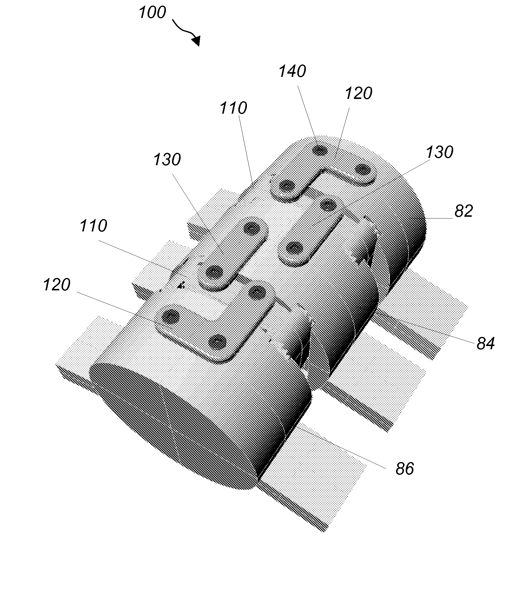
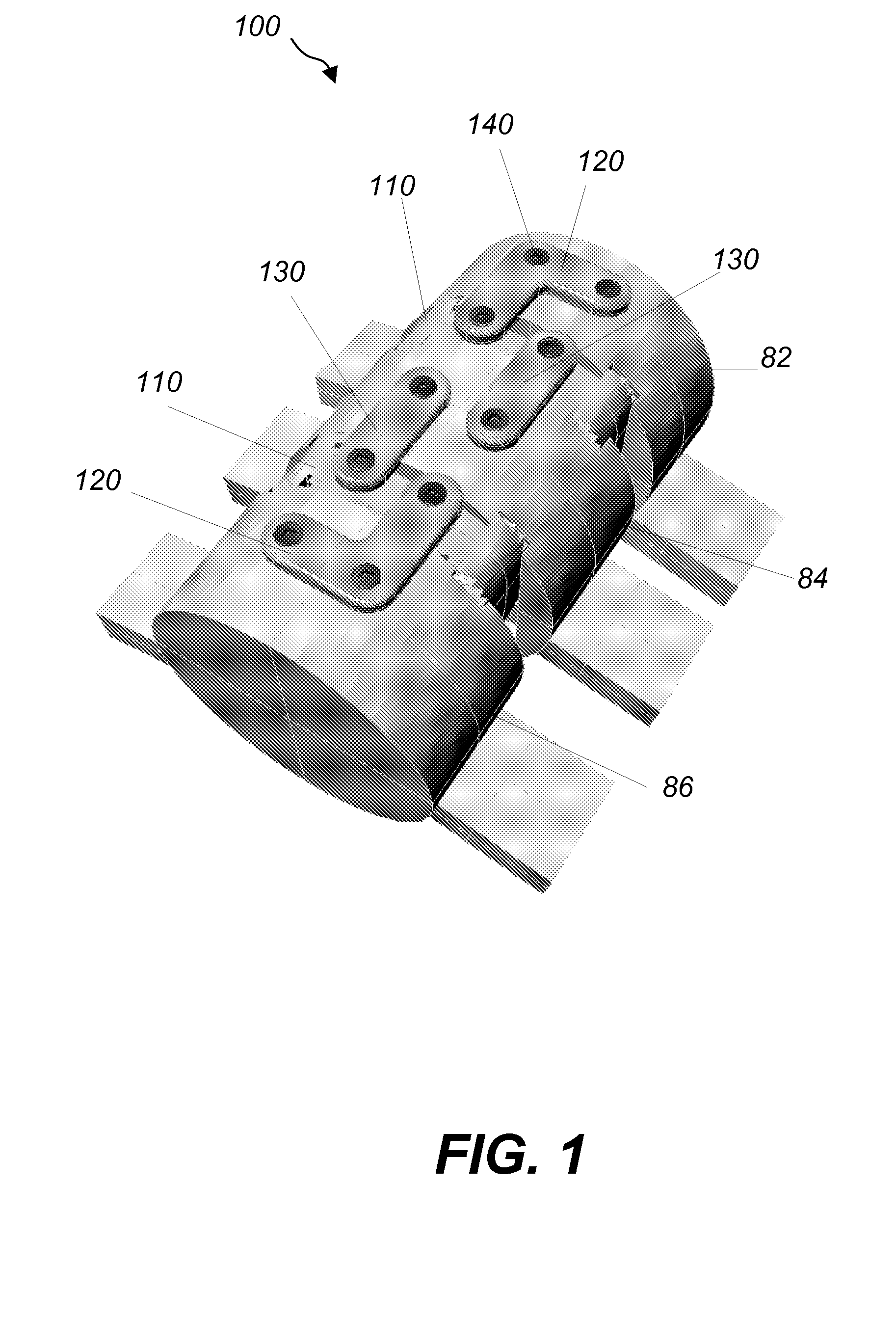
[0031]Referring to FIG. 1, an anterior lumbar interbody fusion (ALIF) assembly 100 includes an intervertebral implant or interbody cage 110 inserted in the disc space between two adjacent vertebras 82 and 84 and two plates 120, 130 securing the interbody cage 110 to the vertebras 82, 84, respectively, with screws 140. Referring to FIG. 2, plate 120 has an L-shaped flat body 124 having ends 126a, 126b. All ends 126a, 126b and corners 127a, 127b are rounded and the body 124 has three through-apertures 122a, 122b, 122c, configured to receive screws 140 for attaching end 126a and corner 127a of the plate 120 to the vertebra 82 and end 126b to the interbody cage 110. Plate 130 has an elongated flat body 134 having rounded ends 136a, 136b. Ends 136a, 136b include through-apertures 132a, 132b, configured to receive screws 140 for attaching ends 136a, 136b to the interbody cage 110 and the adjacent vertebra 84, respectively. In other embodiments plates 120, 130 are T-shaped, H-shaped, I-sha...


PUM

PropertyMeasurementUnit
Lengthaaaaaaaaaa
Widthaaaaaaaaaa
Heightaaaaaaaaaa

Abstract

An improved interbody spinal fusion assembly for fusing a first vertebra to a second vertebra includes an interbody cage, a first plate and a second plate. The interbody cage is configured to be implanted between the first and second vertebras and comprises through-apertures configured to be filled with bone fusing material. The first plate comprises an L-shaped body having a first end configured to be attached to a first location of the interbody cage, a second end configured to be attached to a first location of the first vertebra and a corner formed between the first and second ends and configured to be attached to a second location of the first vertebra or a third location of the interbody cage. The second plate comprises a first end configured to be attached to a second location of the interbody cage and a second end configured to be attached to a first location of the second vertebra.

Description

CROSS REFERENCE TO RELATED CO-PENDING APPLICATIONS[0001]This application claims the benefit of U.S. provisional application Ser. No. 60 / 832,468 filed Jul. 21, 2006 and entitled “SYSTEM AND METHOD FOR FACET FIXATION”, the contents of which are expressly incorporated herein by reference.[0002]This application is also a continuation in part of U.S. application Ser. No. 11 / 174,712 filed on Jul. 5, 2005 and entitled “METHOD AND DEVICE FOR KINEMATIC RETAINING CERVICAL PLATING” the contents of which are expressly incorporated herein by reference.FIELD OF THE INVENTION[0003]The present invention relates to a spinal fusion assembly, and more particularly to a spinal fusion assembly including an interbody cage and a plate system configured to secure the interbody cage to adjacent vertebras.BACKGROUND OF THE INVENTION[0004]The human spine consists of individual vertebras (segments) that are connected to each other. Under normal circumstances the structures that make up the spine function to pr...

Claims


Application Information

Patent Timeline
IPC IPC(8): A61F2/44
CPCA61B17/7059A61F2310/00359A61F2/447A61F2002/2835A61F2002/30062A61F2002/30112A61F2002/30166A61F2002/30168A61F2002/30172A61F2002/30176A61F2002/30179A61F2002/30578A61F2002/30772A61F2002/30904A61F2002/448A61F2002/449A61F2002/4629A61F2210/0004A61F2230/0004A61F2230/0028A61F2230/0043A61F2230/0052A61F2230/0054A61F2230/0058A61F2310/00011A61F2310/00035A61F2310/00071A61F2310/00113A61F2310/00179A61F2/28
Inventor CHIN, KINGSLEY R.CHANG, CHRISTOPHER A.
Owner SPINEFRONTIER LLS
Why Eureka
Try Eureka