Forceps

a forceps and system technology, applied in the field of forceps, can solve the problems of vacuum extrusion carrying its own risks and complications, no reliable way to ensure that excessive force is not applied, and brain damage, scalp and/or facial injuries, etc., to achieve accurate measurement of traction forces through the forceps system, facilitate smooth pivotable relative movement, and sensitive detection of force-induced deformation

Inactive Publication Date: 2014-09-30
PRO MEDICAL INNOVATIONS
View PDF18 Cites 1 Cited by
  • Summary
  • Abstract
  • Description
  • Claims
  • Application Information

AI Technical Summary

Benefits of technology

[0010]By measuring both the compressive and traction forces in real time, it is possible for the operator of the forceps system to know at all times the forces being applied and to adjust the applied forces to avoid the forces being applied from becoming excessive and resulting in damage to the object being held by the forceps system. This invention is particularly, although not exclusively, intended for use during the forceps-assisted childbirth. Thus, being able to monitor the forces being applied to the head of the baby in real time during this process assists in prevention of potential injury to the head and neck of the baby during delivery.
[0020]Preferably, one or more of the strain gauges may be mounted on an external cylindrical surface of the deformable O-ring. In this way, the or each strain gauge will be located at a region of the deformable O-ring that will experience the most deformation during the application of traction forces through the forceps system and thus the or each strain gauge will be located in a position that allows the most sensitive detection of force-induced deformation of the deformable O-ring.
[0021]In a further embodiment, the forceps members are held together by magnetic forces at the point of pivotal engagement between the pair of forceps members. This is achieved by the provision of opposing magnets of opposite polarity, one located on each forceps member at the point of pivotal engagement. The provision of magnetic inter-engagement facilitates smooth pivotable relative movement between the forceps members. Furthermore, the use of the magnetic inter-engagement allows simple disengagement of the forceps members from one another when not in use to facilitate cleaning and / or sterilisation of the forceps members. The simple separation of the forceps members means that the conventional problem of cleaning the forceps system at hinge points is avoided. A further advantage of the use of magnets is that the relative movement of forceps members is possible without any deformation of the deformable O-ring. Thus, any detected deformation of the deformable O-ring is as a result of traction forces through the forceps system and / or compressive forces through respective forceps handle portions.
[0022]A further advantage of the use of magnetic inter-engagement in a forceps system for use in forceps-assisted childbirth is that it assists with the reliable inter-engagement of the forceps members with one another during the engagement process.
[0023]Preferably, the region of pivotal engagement of each forceps member is provided with contours to assist the separation of the forceps members from one another during use. The contours preferably comprise a ramped region whereby rotation of the forceps members relative to one another causes each forceps member to rise up the ramp of the opposing forceps member, thereby separating the forceps members from one another at the point of pivotal engagement. This assists in overcoming the opposing magnetic forces and facilitating ease of separation of the forceps members from one another.

Problems solved by technology

The amount of traction or pressure applied to the skull of the baby during this delivery process is extremely important—sufficient traction or pressure needs to be applied to achieve the desired movement of the baby however, too much traction or pressure can result in injuries to the baby, including brain, scalp and / or facial injuries.
The amount of force applied is subject to the clinical judgement of the medical expert operating the forceps and so there is no reliable way to ensure that excessive force is not applied and that the potential complications for the baby are avoided.
However, vacuum extrusion carries its own risks and complications, including but not limited to haematoma (a blood collection in the scalp).
Although this type of injury is typically resolved without further problems, occasionally life threatening injuries such as subgaleal (subaponeurotic) hematoma, retinal haemorrhages or intracranial haemorrhage may occur.

Method used


Image

  • Forceps
  • Forceps
  • Forceps

Examples


Embodiment Construction

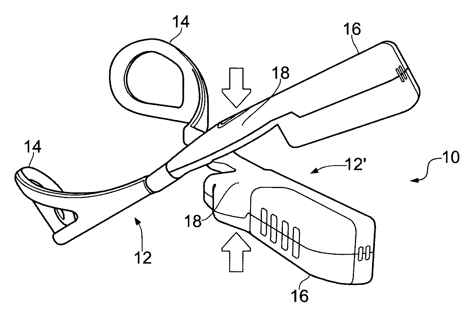
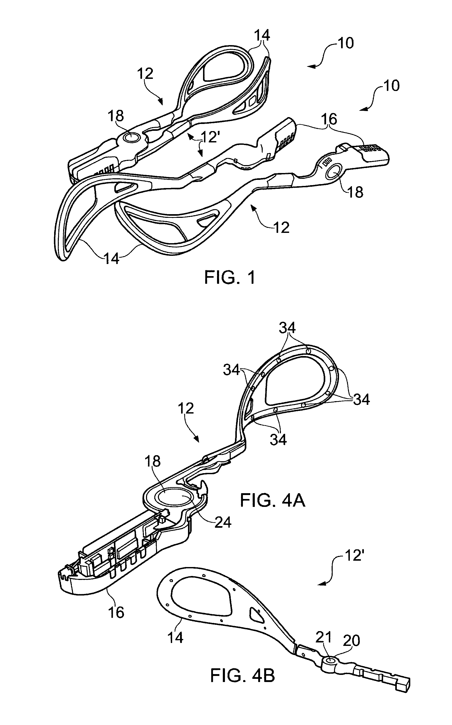
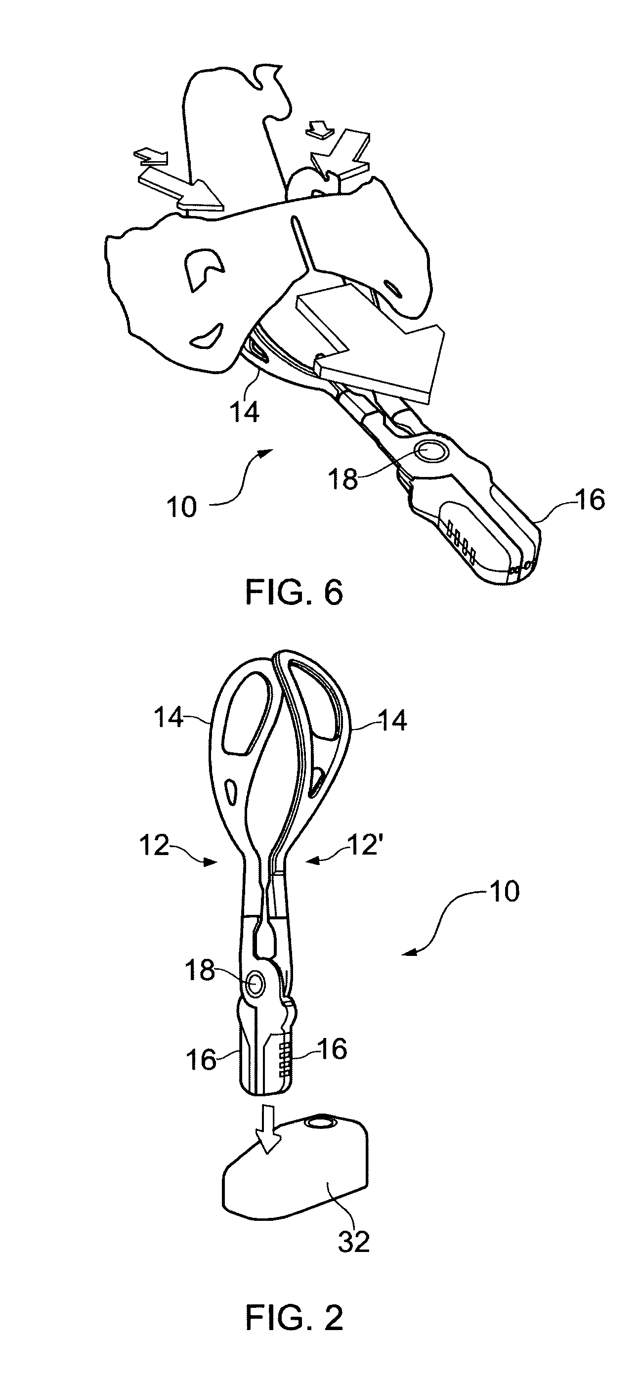
[0044]FIG. 1 shows an embodiment of a forceps system 10 according to a first aspect of the present invention with the forceps members 12, 12′ in an assembled state and also a further two forceps members 12, 12′ in the unassembled state. FIGS. 4A and 4B show components of forceps member 12. The forceps system 10 of FIG. 1 is intended for obstetric use during forceps delivery.

[0045]Each of forceps members 12, 12′ comprises a blade portion 14 at a first end thereof and a respective handle portion 16 at an opposing end thereof, with a respective deformable element in the form of a deformable O-ring 20. The deformable O-ring 20 is composed of a resilient material which deforms under applied force exerted through the forceps system 10.

[0046]It will be appreciated that blade portion 14 of forceps member 12 is a mirror image of blade portion 14 of forceps member 12′. The opposing surfaces of respective forceps blade portions 14, which contact and grip the object to be held therebetween, are...


PUM


Abstract

The invention provides a forceps system comprising a pair of forceps members and force measurement means operable to measure compressive and traction forces exerted by the forceps when in use, and to output measurement signals indicative of such forces. Also provided is a method of measuring the compressive and traction forces exerted by a forceps system when in use.

Description

RELATED APPLICATIONS[0001]The present application is based on, and claims priority from, GB Application Number 0819128.0, filed Oct. 18, 2008, GB Application Number 0908237.1, filed May 13, 2009, and PCT Application Number PCT / GB09 / 002458, filed Oct. 13, 2009, the contents of which are hereby incorporated by reference herein in their entireties.BACKGROUND TO THE INVENTION[0002]The present invention relates to a forceps system for the measurement of compression and traction forces, including the measurement of compression and traction forces exerted upon a fetal head during instrumental delivery.[0003]Forceps are well known for grasping objects by applying pressure to the object to retain it within the forceps then applying force in the desired direction of movement of the object. For example, forceps are used to grasp crucibles of molten metal in order to remove them from a furnace and the like. Similarly, forceps are often used during difficult births to assist with the birthing pr...

Claims


Application Information

Patent Timeline
Patent Type & Authority Patents(United States)
IPC IPC(8): A61B17/44A61B17/00A61B19/00
CPCA61B17/44A61B17/442A61B2019/464A61B2017/00477A61B2017/445A61B2017/00876A61B2090/064
Inventor HARPER, DALE STEVENNALLY, JOHN AIDENTOWNSEND, DAVID JOHNISMAIL, KHALED MOSTAFA KAM
Owner PRO MEDICAL INNOVATIONS
Why Eureka
Try Eureka