Robotic arm and control system

a robot arm and control system technology, applied in the field of robot arms and systems, can solve the problems of position accuracy requirements, degraded accuracy with which an arm can be positioned, and inability to achieve accurate positioning and movement of effectors, so as to achieve efficient and accurate effector positioning and movemen

Active Publication Date: 2009-02-26
ELITE ENG CORP
View PDF21 Cites 70 Cited by
  • Summary
  • Abstract
  • Description
  • Claims
  • Application Information

AI Technical Summary

Benefits of technology

[0008]A robotic arm and control system are presented which overcome the problems noted above, providing efficient and accurate effector positioning and movement under a variety of operating conditions.

Problems solved by technology

However, there are drawbacks associated with this method of operation.
For example, the accuracy with which an arm can be positioned may be degraded as the mechanism's parts become worn.
Positional accuracy requirements may also limit the speed with which the robotic arm can be manipulated, and require that a target object be precisely positioned prior to its being manipulated.

Method used


Image

  • Robotic arm and control system
  • Robotic arm and control system
  • Robotic arm and control system

Examples


Embodiment Construction

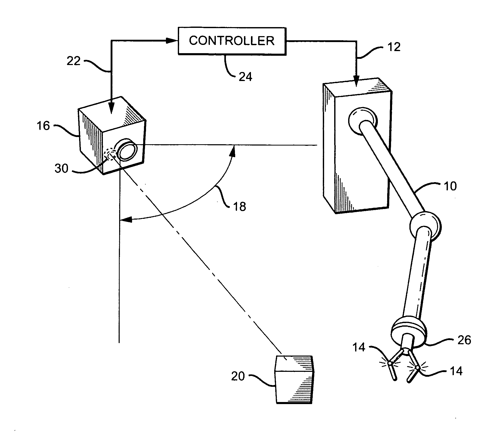
[0019]The basic configuration of a robotic arm and control system in accordance with the present invention is shown in FIG. 1. The system includes a robotic arm 10 which moves in response to one or more command signals 12. There is at least one “active” fiducial 14 located on robotic arm 10. As used herein, an “active” fiducial is one that emits its own light—i.e., it is self-illuminating.

[0020]The system also includes a 3D sensing device 16 having an associated field-of-view (FOV) 18, positioned such that at least one of the fiducials 14 on arm 10, and a target object 20 to be manipulated with the arm, are in the sensing device's FOV. 3D sensing device 16 is preferably a 3D camera, though other types of devices, such as [??], could also be used. However, for simplicity, sensing device 16 is referred to as a 3D camera hereinafter.

[0021]The fiducials are preferably controllable—i.e., they can be activated and deactivated on demand. To determine the spatial positions of the arm and ta...


PUM


Abstract

A robotic arm and control system includes a robotic arm which moves in response to one or more command signals. One or more “active” fiducials are located on the arm, each of which emits its own light. A 3D camera having an associated field-of-view is positioned such that at least one fiducial and a target object to be manipulated are in the FOV. To determine their spatial positions, the arm fiducials are activated and the target object is preferably illuminated with a scanning laser; the camera produces output signals which vary with the spatial locations of the fiducials and target object. A controller receives the output signals and uses the spatial position information as feedback to continuously guide the arm towards the target object. Multiple active fiducials may be employed, each having respective characteristics with which they can be differentiated.

Description

RELATED APPLICATIONS [0001]This application claims the benefit of provisional patent application No. 60 / 966,137 to Robert L. Kay, filed Aug. 24, 2007.BACKGROUND OF THE INVENTION[0002]1. Field of the Invention[0003]This invention relates generally to robotics, and more particularly to robotic arms and systems for controlling such arms.[0004]2. Description of the Related Art[0005]Robotic arms—i.e., articulated mechanisms designed to perform one or more tasks, typically under the control of a computer—are commonly used in factory and assembly line environments. For example, one common task performed by a robotic arm is to grip a target object and then move it to a desired location. This is accomplished with the help of an ‘effector’ mechanism, typically located on the end of a robotic arm; a typical effector is a “gripper” which has at least one movable jaw that is closed in order to grip or grasp a target object.[0006]Traditionally, angle sensors such as encoders are incorporated into...

Claims


Application Information

Patent Timeline
Patent Type & Authority Applications(United States)
IPC IPC(8): B25J9/16
CPCB25J9/1697G05B2219/40623G05B2219/39008G05B2219/37571
Inventor KAY, ROBERT L.
Owner ELITE ENG CORP
Why Eureka
Try Eureka