Slider for slide fastener

Inactive Publication Date: 2009-03-05
YKK CORP
View PDF5 Cites 15 Cited by
  • Summary
  • Abstract
  • Description
  • Claims
  • Application Information

AI Technical Summary

Benefits of technology

[0035]By limiting the direction of the pull tab to a certain direction, the direction of the pull tab when the slide fastener is closed can be specified to a predetermined one, for example, if the slide fastener is used in a seat cover of a vehicle seat. Consequently, when the slider is hidden on the back side of the seat cover, the pull tab does not jump out from the back side of the seat cover even if the slider receives a vibration or the like of the vehicle, whereby the pull tab can be hidden securely. Accordingly, the closing state of the slider fastener can be maintained stably.
[0036]In this case, the rotation blocking means can be easily constructed of the tongue piece projecting from the bridge portion, or can be easily constructed by fixing the pull tab to the bridge portion. If the tongue piece is formed as the rotation blocking means, the direction of the pull tab when the slider is not operated can be oriented in its predetermined direction easily by projecting the tongue piece in a predetermined direction from the bridge portion, for example, to the shoulder mouth side or rear mouth side in parallel to the upper blade.
[0037]In the slider of the present invention, the pull tab is constructed to be bendable elastically. Consequently, the direction of the pull tab can be oriented easily to the sliding direction of the slider when the slider is slid along element rows, so that the slider can be operated smoothly. If the slider has the rotation blocking means, the pull tab can be oriented to a predetermined direction which is limited by the rotation blocking means when the pull tab is released from the fingers. The pull tab may be composed of a hard synthetic resin. Consequently, the pull tab can be constructed to be easy to grip, whereby the sliding operation of the slider can be carried out easily.
[0038]The pull tab of the slider of the present invention is constructed of a narrow thin piece comprised of the first and second pull tab main body portions disposed in the back-forth direction of the slider and the folding portion which con

Problems solved by technology

Although in the conventional slide fastener, the pull tab of the slider is attached considering the operability and the like of the slider, there is such a problem that when the slider is not operated, the metal slider body comes into contact with the connecting portion o

Method used


Image

  • Slider for slide fastener
  • Slider for slide fastener
  • Slider for slide fastener

Examples


Example

First Embodiment

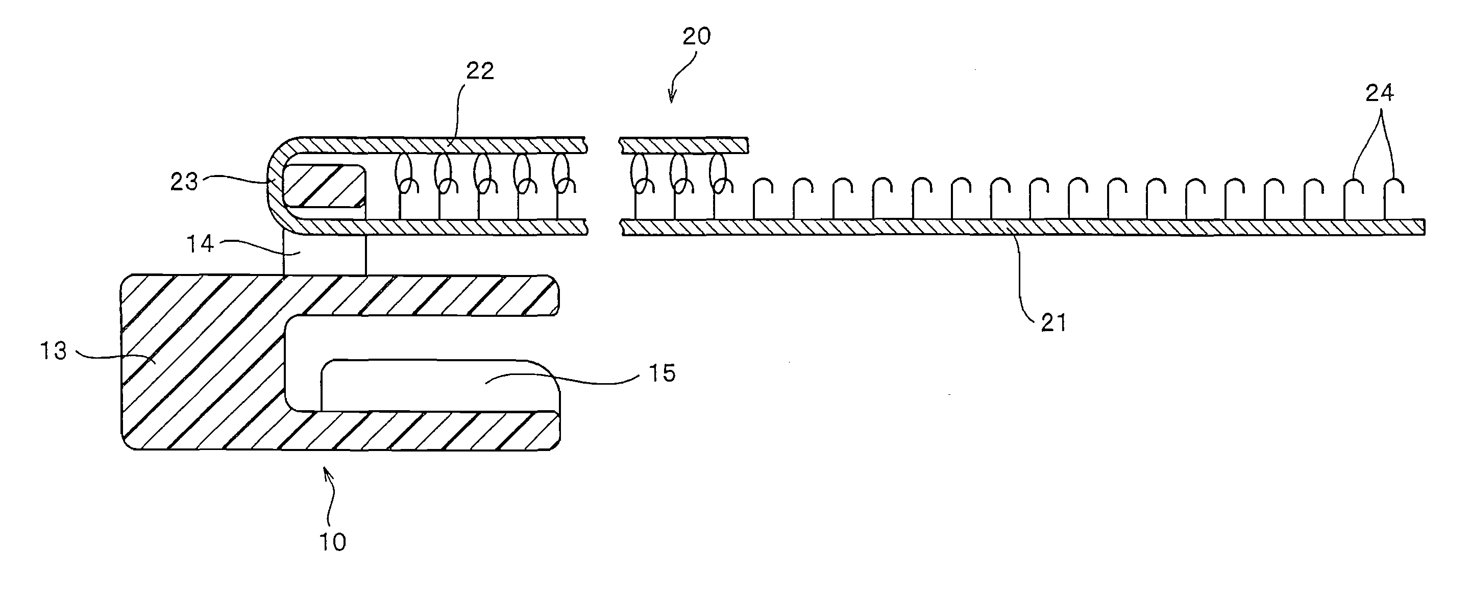
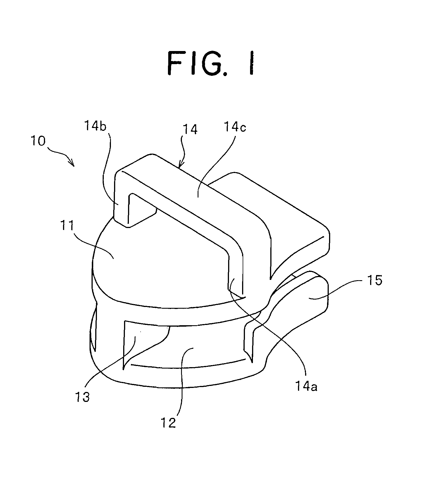
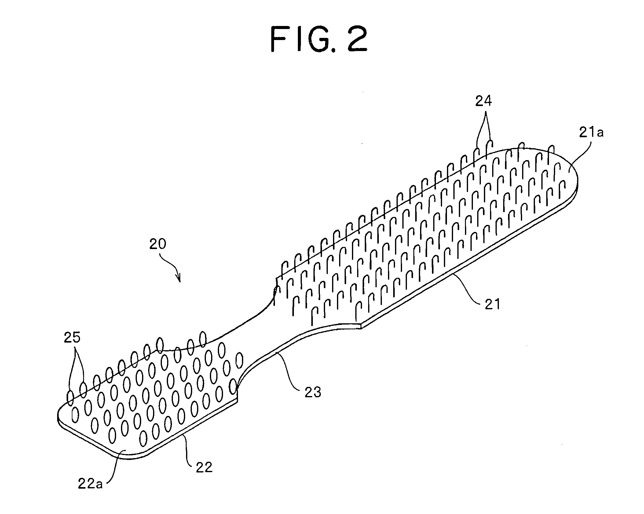
[0058]FIGS. 1 to 3 show a slider for a slide fastener according to a first embodiment of the present invention. FIG. 1 is a perspective view showing a slider body of the slider, and FIG. 2 is a perspective view showing a pull tab of the slider. FIG. 3 is a sectional view showing the section in the back-forth direction of the slider.

[0059]In the description of each embodiment, the back-forth direction of the slider is a direction parallel to the sliding direction of the slider. In the slide fastener, a direction in which the slider is slid to couple right and left elements is assumed to be forward while a direction in which the slider is slid to separate the right and left elements is assumed to be backward. The right and left direction of the slider is a direction at right angle to the back-forth direction of the slider and parallel to the fastener tape plane when the slide fastener is constructed, and the up-down direction of the slider is the same direction as the ...

Example

Second Embodiment

[0086]Next, a slider for a slide fastener according to a second embodiment of the present invention will be described. FIG. 9 is a side view schematically showing the slider for a slide fastener according to the second embodiment. In the second embodiment and third to fifth embodiments described later, like reference numerals are attached to components and member having the same structure as the first embodiment, and description thereof is omitted.

[0087]A slider 41 of the second embodiment shown in FIG. 9 has a slider body 10 and a pull tab 42. The slider body 10 has the same configuration as the first embodiment. On the other hand, the pull tab 42 of the second embodiment is formed of a woven narrow thin belt-like body. The pull tab 42 has first and second pull tab main body portions 43, 44 each having the same length disposed in the back-forth direction of the slider and a folding portion 45 for connecting the pull tab main body portions 43 and 44.

[0088]The first ...

Example

Third Embodiment

[0093]Subsequently, a slider for a slide fastener according to a third embodiment of the present invention will be described. FIG. 10 is a side view schematically showing the slider for a slide fastener of the third embodiment.

[0094]A slider 46 shown in FIG. 10 includes a slider body 10′ and a pull tab 47. In this slider body 10′, the shape of a pull tab attaching post 14′ is changed with respect to the slider body 10 of the first and second embodiments; a bridge portion 14c′ stretched between right and left leg portions 14a′ and 14b′ is formed cylindrically; and a pull tab insertion slit is provided in a substantially central portion of the bridge portion 14c′. In the meantime, other configuration than the pull tab attaching post 14′ of the slider body 10′ is the same as the slider body 10 of the first and second embodiments.

[0095]The pull tab 47 is formed by molding a synthetic resin. The pull tab 47 includes a pull tab main body portion 48 disposed in the back-for...


PUM


Abstract

The present invention provides a slider for a slide fastener, capable of preventing any sound from being generated by reducing contact sound from a slider body or a pull tab without affecting operability of the slide fastener. There is provided a slider for a slide fastener including a slider body, further including: a gate-shaped pull tab attaching post having right and left leg portions erected from the upper blade and apart from each other in a transverse direction of the slider body and a bridge portion stretched between the top end portions of the right and left leg portions, the pull tab attaching post being formed integrally with the slider body; and a pull tab, one end of which is attached to the bridge portion, the pull tab extending from the bridge portion.

Description

BACKGROUND OF THE INVENTION[0001]1. Field of the Invention[0002]The present invention relates to a slider for a slide fastener, capable of reducing sound generated by a contact between a slider body and a pull tab.[0003]2. Description of the Related Art[0004]Conventionally, a slide fastener is attached to an opening in order to easily open / close the opening in clothes, bag or the like. Generally, the slide fastener is constructed by arranging a plurality of fastener elements on each of element attaching edge portions opposing each other of right and left fastener tapes so as to form a pair of right and left fastener stringers, and then placing a slider on the right and left element rows composed of the plurality of fastener elements disposed on the right and left fastener stringers.[0005]A slider has a slider body to be placed on the element rows and a pull tab attached to the slider body. The slider body is often made of metal and generally, includes upper and lower blades, a conne...

Claims


Application Information

Patent Timeline
IPC IPC(8): A44B19/26
CPCA44B19/26Y10T24/2586A44B19/262
Inventor UJIHARA, MASAHIROKEYAKI, KEIICHIDOI, MASASHI
Owner YKK CORP
Why Eureka
Try Eureka