Decapping system

a decapping system and vacuum technology, applied in the direction of rotating screw stopper insertion, liquid handling, instruments, etc., can solve the problems of evaporation of considerable amounts of reagent solution, the dwell time of the reagent cartridge is relatively long, and the inability to pierce the funnel with the pipetting needle,

Active Publication Date: 2009-03-05
ROCHE DIAGNOSTICS OPERATIONS INC
View PDF31 Cites 26 Cited by
  • Summary
  • Abstract
  • Description
  • Claims
  • Application Information

AI Technical Summary

Benefits of technology

[0024]These and other features and advantages of the invention will be more fully understood from the f

Problems solved by technology

The reagent cartridge has a relatively long dwell time on the device, because of the low throughput.
Because of the short cycle time, piercing of the funnels with the pipetting needle is not possible.
Especially in rooms with low atmospheric humidity, considerable amounts of the reagent solution are often lost through evaporation.
Moreover, when open reagent containers are used, there is an exchange of gas with the surrounding air, which among other things causes ageing of a reagent.
Such effects on the reagent, in particular in the reagent concentration, result in a deterioration in the analysis precision.
It has additionally been found that a removal of the reagent closure often has to be done manually.
Since it often happens that many different reagents are needed at different times in one and the same analysis system, a manual handling by laboratory personnel requires considerable labor and time.
In procedures carried out manually, the possible confusion of the closures represents a source of uncertainty.
However, the prior art described herein discloses only an automatic opening of reagent vessels closed by a stopper.
A disadvantage of the prior art

Method used


Image

  • Decapping system
  • Decapping system
  • Decapping system

Examples


first embodiment

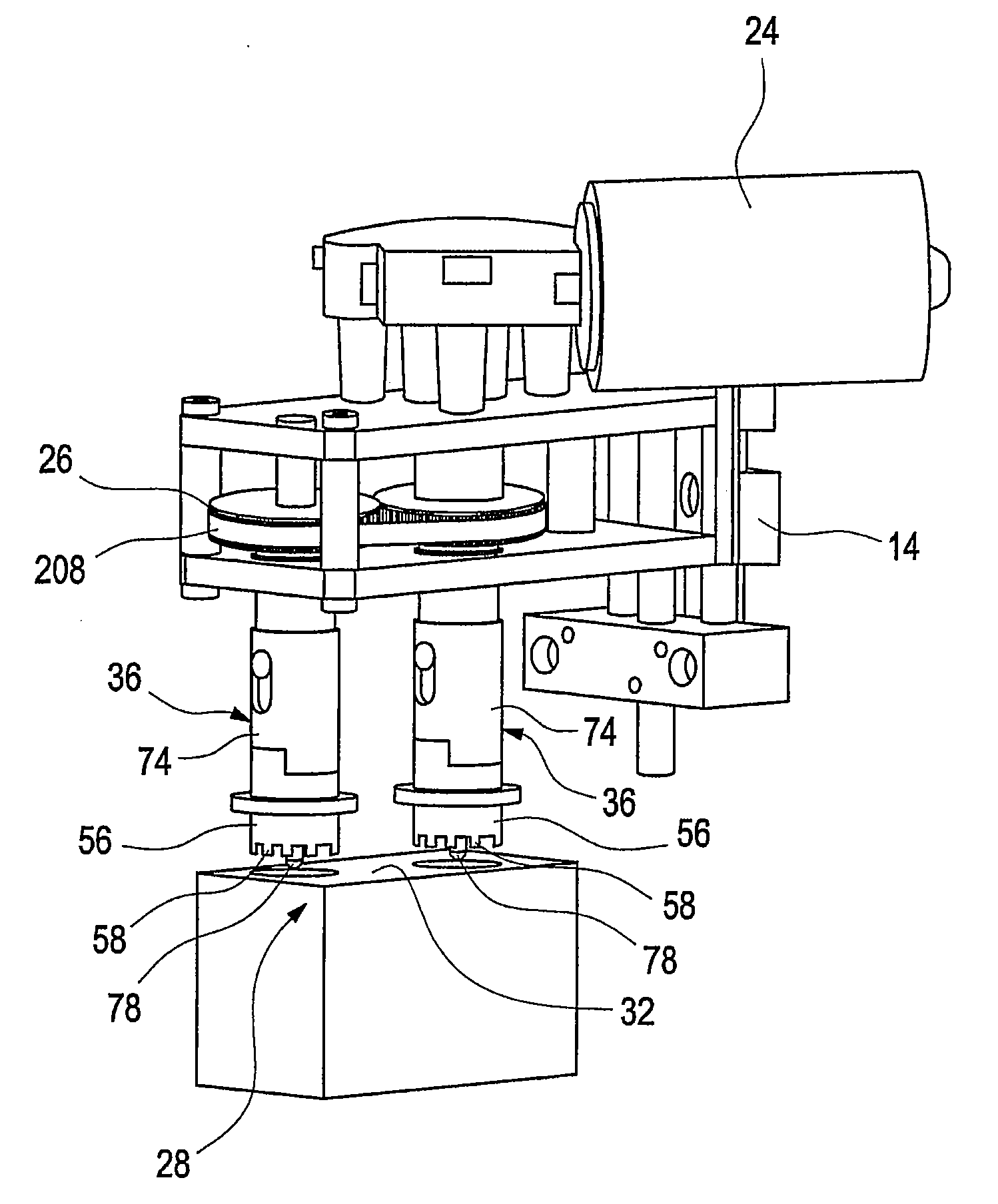
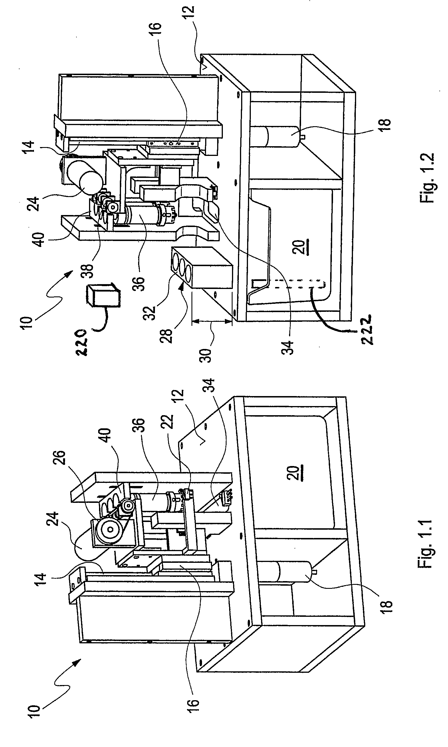
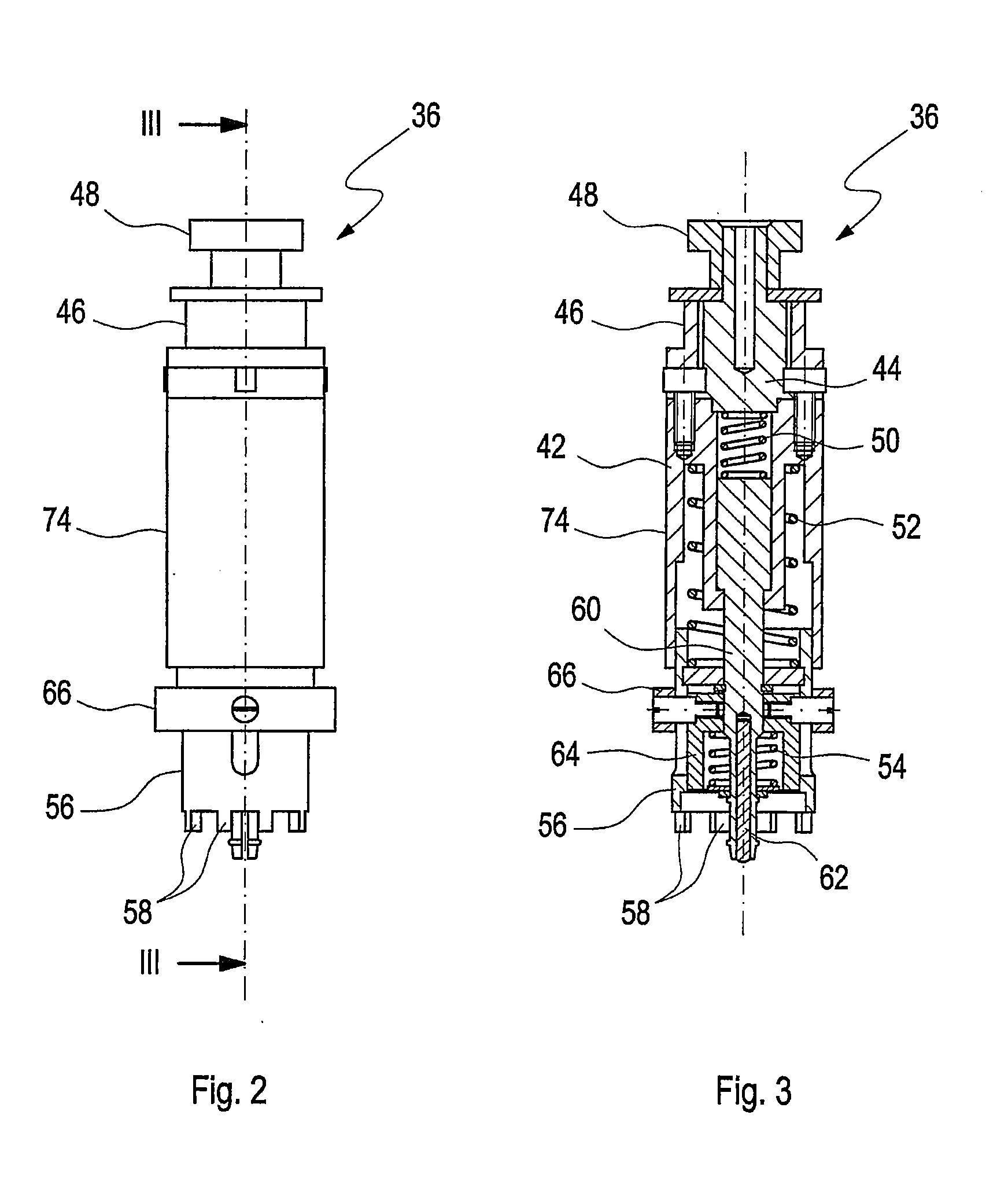
[0040]FIGS. 1.1 and 1.2 show different perspective views of the present invention. FIG. 1.1 shows a decapping system 10 comprising a table, the surface of which is labeled with reference numeral 12. In vertical direction, a linear guide 14 is mounted on the surface 12 of the decapping system 10. By means of a linear drive 16, movable vertically along the linear guide 14, a plurality of screwing heads 36 is moved in vertical direction. From the linear drive 16, a screwing head drive 24 is mounted, driving a screwing head gear 26.

[0041]The screwing head gear 26 preferably comprises a worm / gear arrangement with which the plurality of screwing heads 36 is driven rotationally. With respect to the linear drive 16, the plurality of screwing heads 36 is mounted in substantially vertical direction, i.e. parallel to the direction of vertical movement of the linear drive, i.e. the Z-direction. The vertical movement of the linear drive 16, to which the plurality of screwing heads 36 is attached...

second embodiment

[0068]FIG. 10 shows a cartridge system mounting area of the second embodiment given in FIG. 9. According to the detailed perspective view in FIG. 10, the cartridge system 28 is introduced into a guiding passage 201. The cartridge system 28 is arranged upon the adapting device 200 having a height compensation indicated by reference numeral 206. By means of the adapting device 200, the upper cartridge surface 32 is moved into the direction of the crown-shaped screwing ring 56 having a number of tooth-shaped protrusions 58 arranged along its outer circumference. The cartridge system 28 within the guiding passage 201 is fixed by an actuatable pin-shaped positioning element 205 engaging a positioning opening 204 on the upper cartridge surface 32 of the cartridge system 28 to be processed. The full introduction of the cartridge system 28 into the guiding passage 201 underneath the screwing head 36 is detected by means of micro-switches 22, 68, 70 and 72, which further initiate and stop th...


PUM

PropertyMeasurementUnit
Forceaaaaaaaaaa
Sizeaaaaaaaaaa
Speedaaaaaaaaaa

Abstract

Decapping system for opening or closing reagent containers or cartridge systems closed by a lid the which is removed and secured by a rotational movement and method thereof are disclosed. The decapping system has a centering unit that the at its lower end provides a snap-in element which engages the lid, and a plurality of simultaneously driven and vertically movable screwing heads which compensates for variable heights and/or sizes of cartridge systems to be processed.

Description

FIELD OF THE INVENTION[0001]The present invention is related generally to automatic analysis devices, and in particular to a decapping system for automatic analysis devices in which a large number of reagents can be simultaneously accommodated and processed.BACKGROUND OF THE INVENTION[0002]It is desirable to permit, as far as possible, fully automatic handling of samples and reagents in analysis devices, so that no manual handling steps are necessary. This allows for simplification and acceleration of many analysis procedures and, still further, reduction of mistakes due to human error during the analysis procedure.[0003]Stringent demands are placed on automatic analysis devices, especially in large-scale laboratories in which a high sampling rate must be permitted. Here, the analysis devices must be able to deliver the large number of reaction vessels with different samples and must be able to allocate these to different reagent containers. In this respect, pipetting devices, inter...

Claims


Application Information

Patent Timeline
IPC IPC(8): B65B43/40B23P19/04B65B43/00
CPCG01N35/04Y10T29/53687G01N2035/0491G01N2035/0405
Inventor KRAMER, REINHOLDSATTLER, STEPHANMERTSCH, UWE
Owner ROCHE DIAGNOSTICS OPERATIONS INC
Why Eureka
Try Eureka