
Sliding Rail Structure for Use in Cuckoo Clocks

a technology for sliding rails and cuckoo clocks, applied in friction gearings, instruments, gearing, etc., can solve the problems of cuckoo clocks that cannot be securely pressed, extremely dull time telling way, etc., and achieve the effect of preventing disengagemen

Inactive Publication Date: 2009-03-05
TSAI CHZNG TZEN
View PDF5 Cites 7 Cited by
  • Summary
  • Abstract
  • Description
  • Claims
  • Application Information

AI Technical Summary

Benefits of technology

[0008]The primary object of the present invention is to provide a sliding rail structure for use in cuckoo clocks that may prevent the disengagement of the sliding piece for causing a stable reciprocating movement.
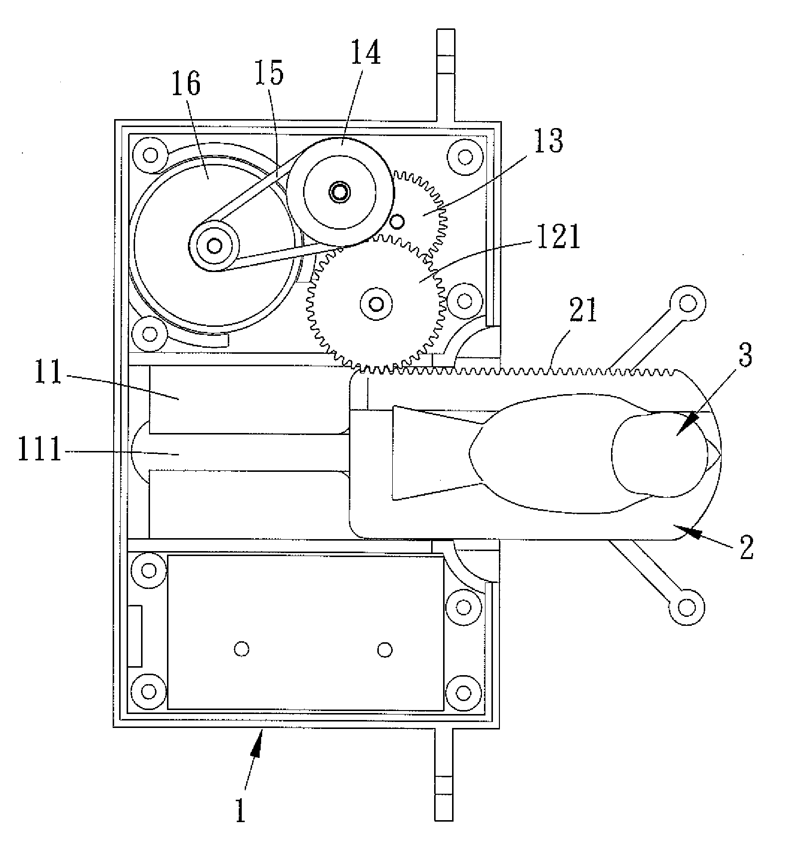
[0009]In accordance with one aspect of the present invention, there is provided a sliding rail structure for use in cuckoo clocks comprising a base, an elongated sliding piece, a cuckoo element, a casing, a housing, a confining element, and a covering member, wherein the base includes a guiding member provided thereon and having an elongated slot formed at the center thereof, and includes a double gear disposed on one side of the guiding member. The double gear is comprised of an upper gear and a lower gear, and the upper gear is engaged with a pulley by using a spur gear, the pulley is coupled to a shaft of a motor by way of a belt. The elongated sliding piece includes a rack mounted on one side thereof, and includes an engaging recess formed on the top surface of the front end thereof, includes a peg fixed on the bottom surface of the rear end thereof and having a hole formed therein. The cuckoo element includes a stem affixed on the bottom thereof, and the casing includes a top panel arranged thereon, and includes a side panel secured on the right side of the top panel and extending downwardly. The housing includes a top plate arranged thereon, and includes a side plate secured on the left side of the top plate, extending downwardly, and having a notch attached thereon. Besides, the confining element is a screw for generating a stopping effect.

Problems solved by technology

For example, a prior art clock tells time at the right clock by making sounds, nevertheless, such a time telling way is extremely dull.
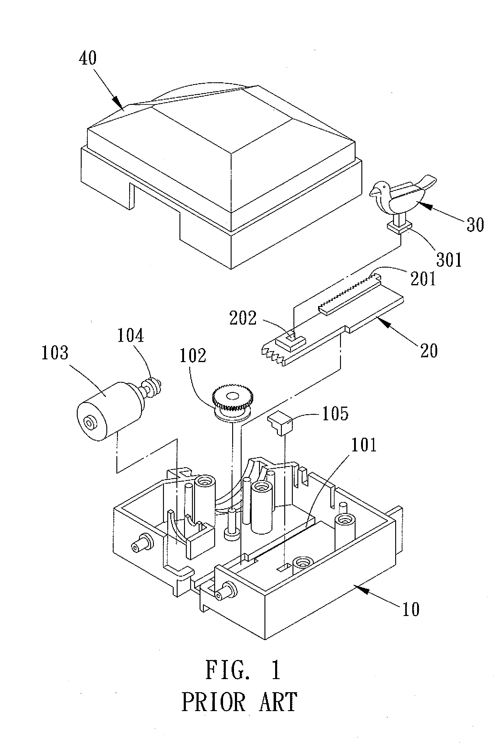
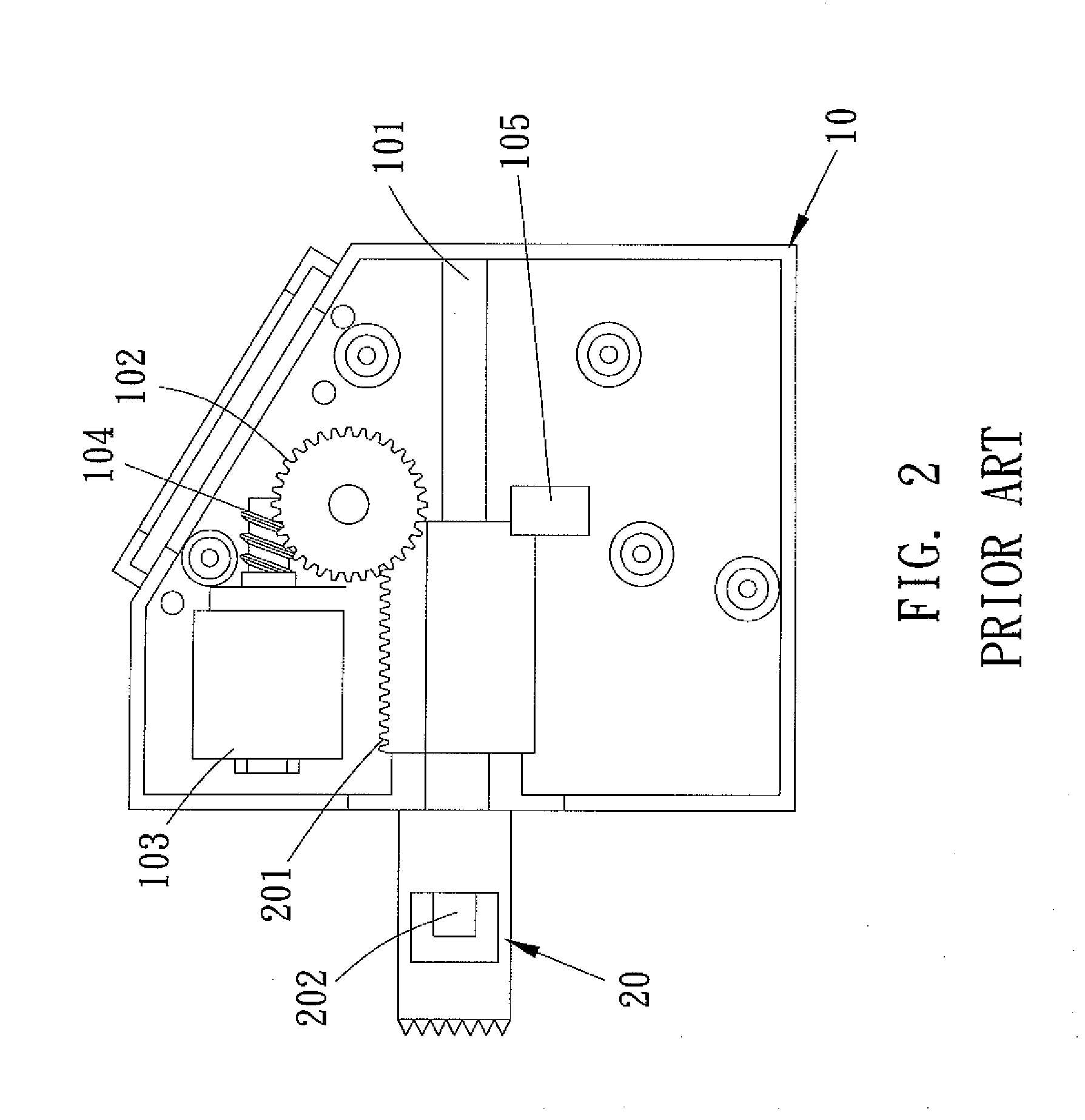
However, the sliding piece 20 of the prior art sliding rail structure for use in cuckoo clocks can not be securely pressed by the positioning projection 105 and the double gear 102, occurring a disengagement or an unstable movement.

Method used


Image

  • Sliding Rail Structure for Use in Cuckoo Clocks
  • Sliding Rail Structure for Use in Cuckoo Clocks
  • Sliding Rail Structure for Use in Cuckoo Clocks

Examples


Embodiment Construction

[0019]Referring to FIGS. 3-5, a sliding rail structure for use in cuckoo clocks in accordance with the present invention comprises a base 1, an elongated sliding piece 2, a cuckoo element 3, a casing 4, a housing 5, a confining element 6, and a covering member 7, wherein the base 1 includes a guiding member 11 provided thereon and having an elongated slot 111 formed at the center thereof, and includes a double gear 12 disposed on one side of the guiding member 11. The double gear 12 is comprised of an upper gear 121 and a lower gear 122, and the upper gear 121 is engaged with a pulley 14 by using a spur gear 13, the pulley 14 is coupled to a shaft of a motor 16 by way of a belt 15. The elongated sliding piece 2 includes a rack 21 mounted on one side thereof, and includes an engaging recess 22 formed on the top surface of the front end thereof, and includes a peg 23 fixed on the bottom surface of the rear end thereof and having a hole formed therein. The cuckoo element 3 includes a s...


PUM


Abstract

A sliding rail structure for use in cuckoo clocks comprises a base including a guiding member provided thereon and having an elongated sliding piece correspondingly fixed thereon, the sliding piece including a rack mounted on one side thereof, and including an engaging recess formed on the front end thereof for inserting a stem of a cuckoo element, characterized in a casing and a housing are fixed onto the base for pressing against the two sides of the sliding piece, respectively, thus obtaining a stable reciprocating movement of the sliding piece, and the guiding member further includes an elongated slot formed at the center thereof, a peg is extendedly arranged on the bottom of the sliding piece for being fitted into the guide slot of the guiding member, and for screwing a confining element therein, thereby preventing the disengagement of said sliding piece for causing a stopping effect.

Description

BACKGROUND OF THE INVENTION[0001]1. Field of the Invention[0002]The present invention relates to a sliding rail structure, and more particularly to a sliding rail structure for use in cuckoo clocks that may prevent the disengagement of the sliding piece for causing a stable reciprocating movement.[0003]2. Description of the Prior Arts[0004]Generally, a clock is provided to tell time in a variety of different manners. For example, a prior art clock tells time at the right clock by making sounds, nevertheless, such a time telling way is extremely dull. To overcome this problem, a cuckoo clock has been developed, wherein a cuckoo element is urged to extend outward from the interior of the clock for telling time at the right clock.[0005]Referring to FIGS. 1 and 2, a prior art sliding rail structure for use in cuckoo clocks comprises a base 10 including a guiding slot 101 provided thereon and having an elongated sliding piece 20 correspondingly fixed thereon, the sliding piece 20 includi...

Claims


Application Information

Patent Timeline
Patent Type & Authority Applications(United States)
IPC IPC(8): F16H19/04G04B25/06
CPCY10T74/18088G04B25/06
Inventor TSAI, CHZNG-TZEN
Owner TSAI CHZNG TZEN
Learn More