Modularly constructed conveyor belt, and module

Active Publication Date: 2009-03-05
AMMERAAL BELTECH BV
View PDF6 Cites 6 Cited by
  • Summary
  • Abstract
  • Description
  • Claims
  • Application Information

AI Technical Summary

Benefits of technology

[0008]The object of the invention is to provide a conveyor belt in which the

Problems solved by technology

A disadvantage of known modular conveyor belts produced according to the abovementioned principle is the relatively long run-in length and run-out length of a bend, which according to current guidelines is at le

Method used


Image

  • Modularly constructed conveyor belt, and module
  • Modularly constructed conveyor belt, and module
  • Modularly constructed conveyor belt, and module

Examples


Embodiment Construction

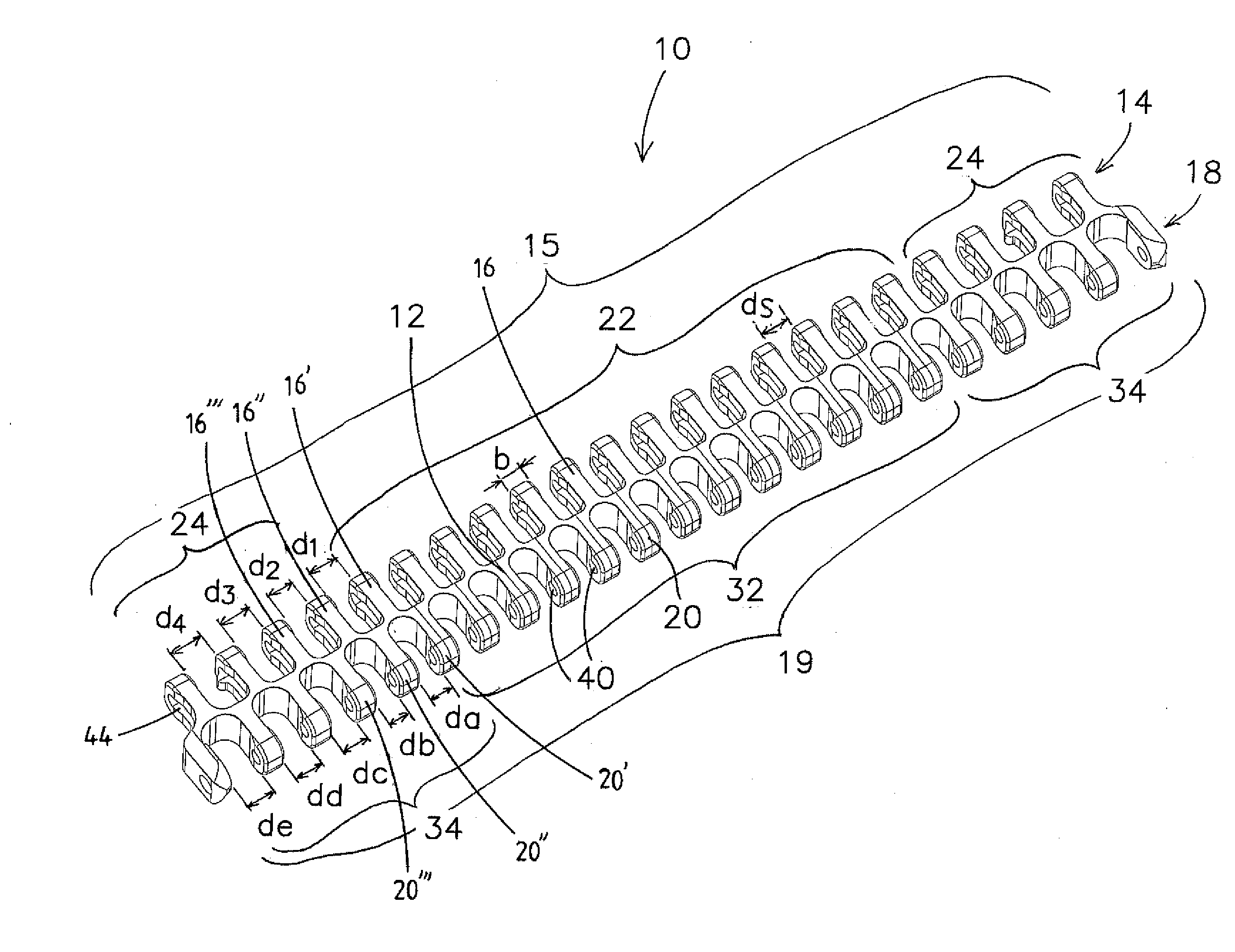
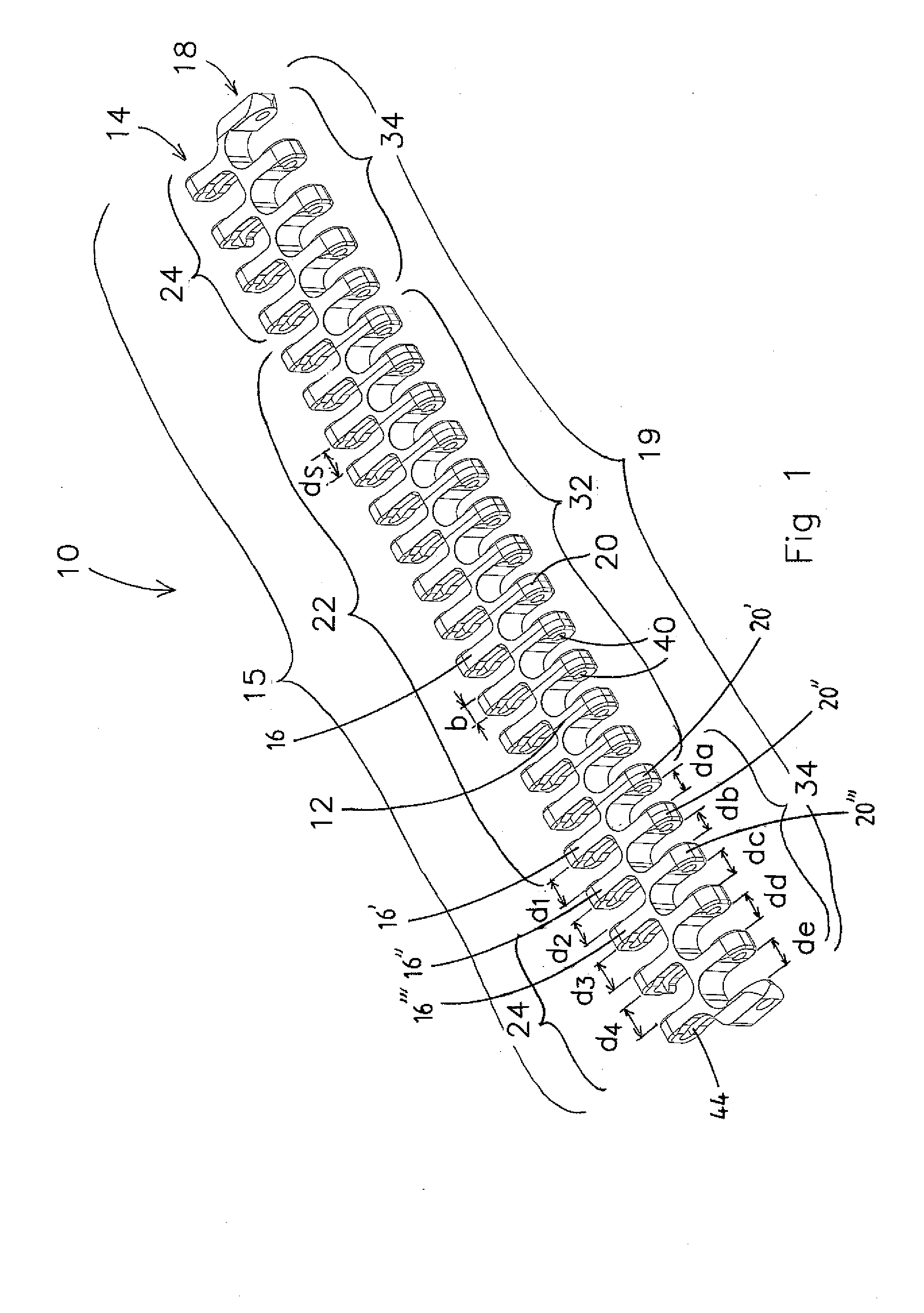
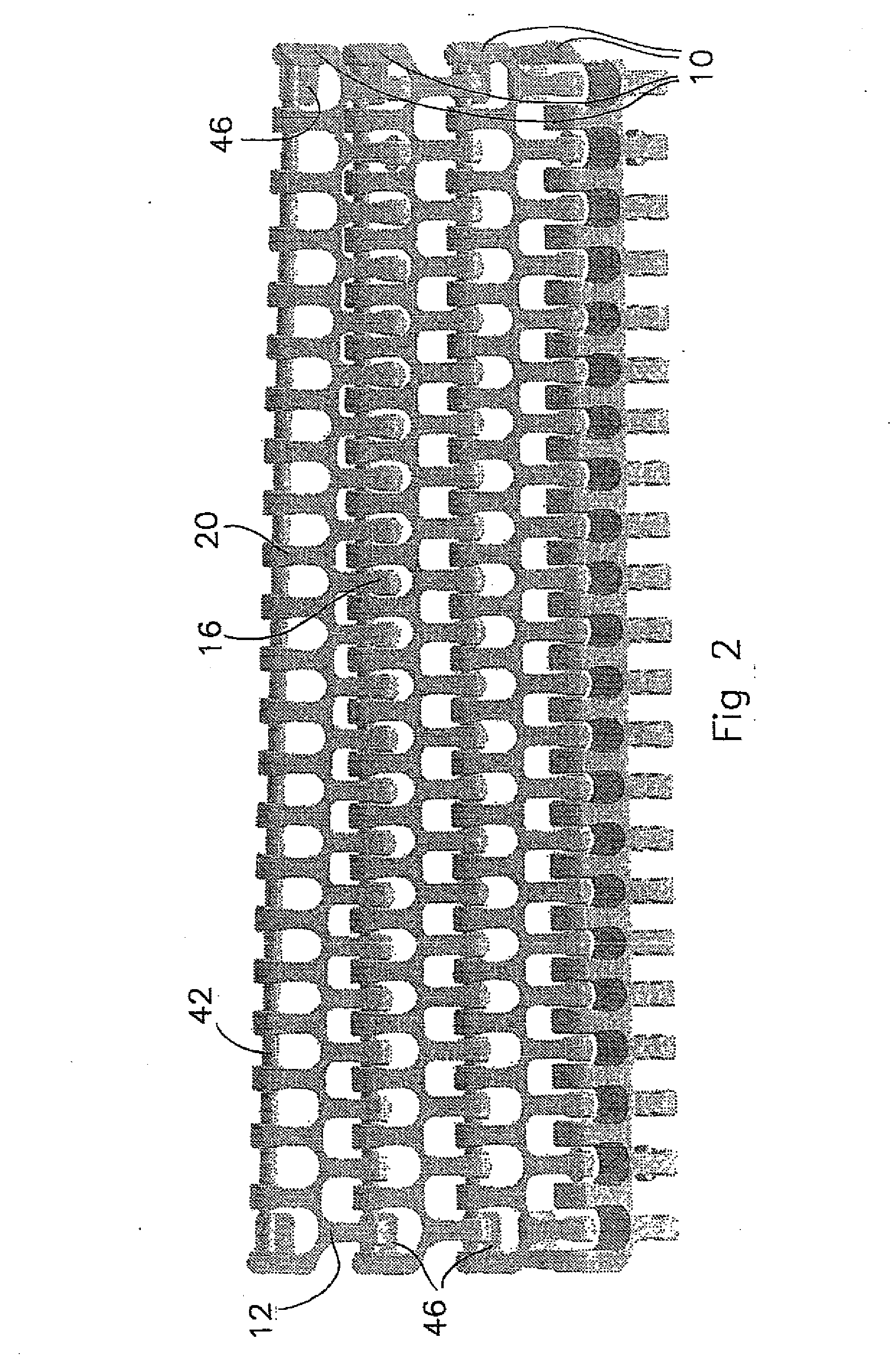
[0024]The embodiment of a module 10 according to the invention shown in perspective in FIG. 1 comprises a base element 12 having on a first longitudinal side 14 thereof a first set 15 of first fingers 16, and on the opposite longitudinal side 18 a second set 19 of second fingers 20. The fingers 16 and 20 are staggered relative to each other in the widthwise direction. The fingers of a set in this embodiment are all of the same width b. The first set 15 comprises in the centre a second sub-group 22 of fingers 16, which are situated at a standard distance ds from each other. Situated on either side of the second sub-group 22 is a first sub-group 24 of four fingers 16 each in the case illustrated. The distance d1 between the outermost finger 16′ of the second sub-group 22 and the innermost finger 16″ of a first sub-group 24 is greater than the standard distance ds. The distance d2 between the innermost finger 16″ of the first sub-group 24 and the adjacent finger 16′″ of the same sub-gr...


PUM


Abstract

A conveyor belt for following a conveyance path with straight and curved conveyance path sections is constructed of module rows of a module (10) or a plurality of modules situated side by side in the transverse direction of the conveyor belt. Adjacent module rows are connected to each other by means of connecting pins (42). Each module comprises a set (15) of first aligned spaced fingers (16) with transverse aperture (40), and also a set (19) of second aligned spaced fingers (20) with transverse aperture (44), which in general are disposed in a staggered position relative to the first fingers (16). The mutual distance between at least the three outermost fingers of a set situated side by side and having the same width in a set is greater than the mutual distance between fingers situated side by side at a distance from the abovementioned at least three outermost fingers. A shorter run-in length and run-out length of a curved conveyance section of the conveyance path is achieved in this way.

Description

CROSS-REFERENCE TO RELATED APPLICATIONS [0001]This application is claims the benefit of Netherlands Application No. 1034297, filed Aug. 28, 2007, the contents of which is incorporated by reference herein.FIELD OF THE INVENTION [0002]The invention relates to a conveyor belt for following a conveyance path with straight and curved conveyance path sections.BACKGROUND OF THE INVENTION [0003]A conveyor belt is known, for example from the publication U.S. Pat. No. 5,547,071. This known conveyor belt is constructed of module rows, each module row comprising one or more modules made of plastic situated side by side in the transverse direction of the conveyor belt. Each module has a set of first aligned spaced fingers extending in a first direction from a module element disposed transversely to the longitudinal direction of the conveyor belt. A set of second aligned spaced fingers extends in the opposite direction from the base element. The second fingers are generally disposed in a staggere...

Claims


Application Information

Patent Timeline
IPC IPC(8): B65G17/06
CPCB65G17/086
Inventor PAARDEKOOPER, JACOBUS GERARDUS MARIABUTER, GERM
Owner AMMERAAL BELTECH BV
Why Eureka
Try Eureka