Method for transmitting image data to driver of display

Active Publication Date: 2009-03-05
HIMAX TECH LTD
View PDF40 Cites 3 Cited by
  • Summary
  • Abstract
  • Description
  • Claims
  • Application Information

AI Technical Summary

Benefits of technology

[0010]For the foregoing embodiments of the present invention, the method for transmitting image data to a driver of a display is capable of r

Problems solved by technology

However, when the transmission becomes faster, the electromagnetic interference (EMI) radiation a

Method used


Image

  • Method for transmitting image data to driver of display
  • Method for transmitting image data to driver of display
  • Method for transmitting image data to driver of display

Examples


first embodiment

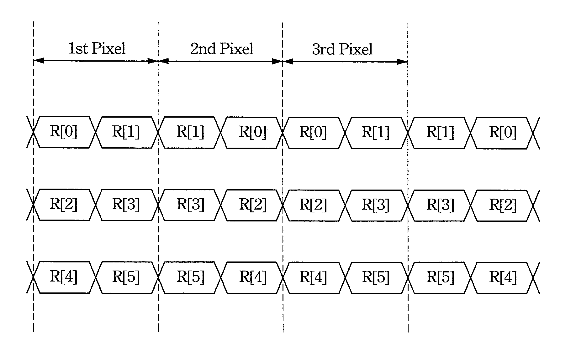
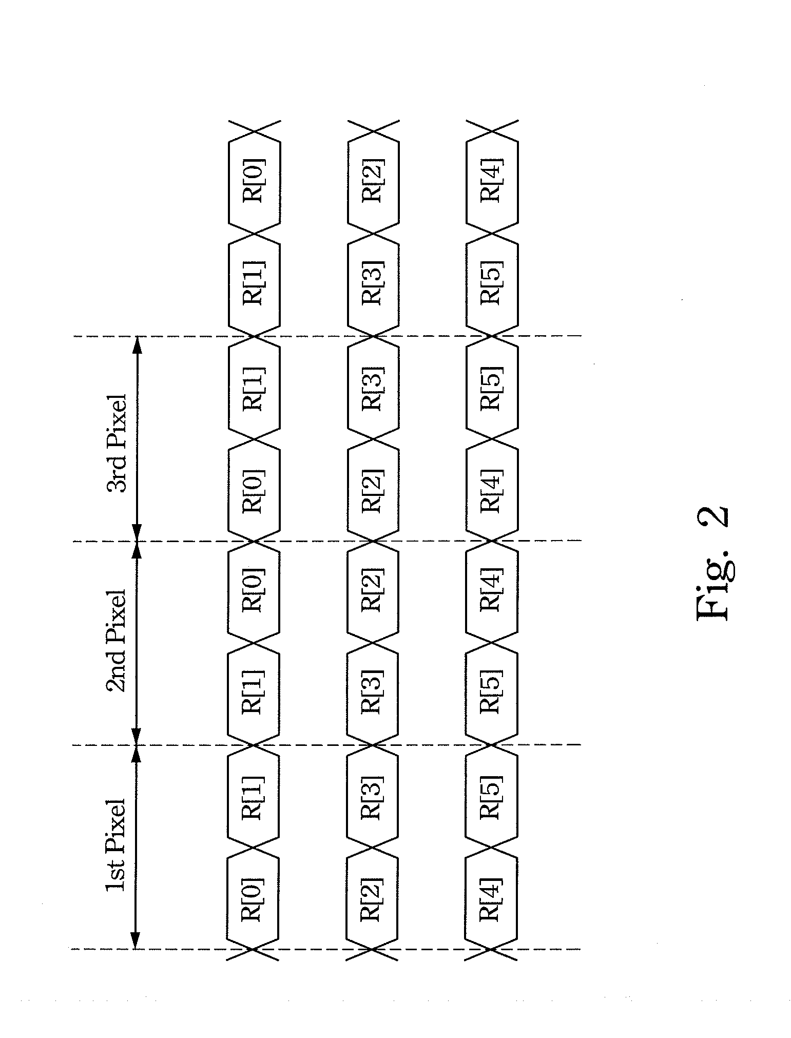
[0020]FIG. 2 shows the pixel value waveforms when using the method for transmitting the image data according to the present invention. As shown, when each pixel value is represented by six bits, i.e. R[0], R[1], . . . , R[5], the six bits of each pixel value are transmitted through three of the data lines. During the first period, the six bits of the first pixel value are sequentially transmitted through three of the data lines, respectively; that is, R[0] and R[1] are sequentially transmitted through one of the data lines, R[2] and R[3] are sequentially transmitted through another one of the data lines, and R[4] and R[5] are sequentially transmitted through yet another one of the data lines.

[0021]During the second period after the first period, the six bits of the second pixel value are sequentially transmitted through the data lines as well, in which the order of the last bit transmitted during the first period is the same as that of the first bit transmitted during the second per...

second embodiment

[0023]FIG. 3 shows the pixel value waveforms when using the method for transmitting the image data according to the present invention. The six bits of each pixel value are transmitted through two of the data lines. During the first period, the six bits of the first pixel value are sequentially transmitted through two of the data lines, respectively; that is, R[0], R[1] and R[2] are sequentially transmitted through one of the data lines, and R[3], R[4] and R[5] are sequentially transmitted through the other one of the data lines.

[0024]During the second period after the first period, the six bits of the second pixel value are sequentially transmitted through the data lines as well, in which the order of the last bit transmitted during the first period is the same as that of the first bit transmitted during the second period; that is, R[2], R[1] and R[0] are sequentially transmitted through one of the data lines, and R[5], R[4] and R[3] are sequentially transmitted through the other on...

third embodiment

[0026]FIG. 4 shows the pixel value waveforms when using the method for transmitting the image data according to the present invention. Compared to FIG. 3, the six bits of the first pixel value are transmitted through two of the data lines, respectively, and transmitted alternately by one bit through the data lines during the first period; that is, R[0], R[2] and R[4] are sequentially transmitted through one of the data lines, and R[1], R[3] and R[5] are sequentially transmitted through the other one of the data lines.

[0027]During the second period after the first period, the six bits of the second pixel value are sequentially transmitted through the data lines as well, in which the order of the last bit transmitted during the first period is the same as that of the first bit transmitted during the second period; that is, R[4], R[2] and R[0] are sequentially transmitted through one of the data lines, and R[5], R[3] and R[1] are sequentially transmitted through the other one of the da...


PUM


Abstract

A method for transmitting image data to a driver of a display is provided, in which the image data include pixel values each represented by a number of bits. The method includes the steps of sequentially transmitting at least two bits of one of the pixel values during a first period through a data line; and sequentially transmitting at least two bits of another one of the pixel values during a second period next to the first period through the data line, in which an order of the last bit transmitted during the first period is the same as that of the first bit transmitted during the second period.

Description

BACKGROUND[0001]1. Field of Invention[0002]The present invention relates to a method for transmitting image data. More particularly, the present invention relates to a method for transmitting image data to a driver of a liquid crystal display.[0003]2. Description of Related Art[0004]In a display system, pixel values of image data are typically transmitted one by one through a number of data lines. More specifically, when bits of one of the pixel values are transmitted, the bits changing in a time series manner are transmitted in parallel from a transmitter to a receiver.[0005]FIG. 1 shows the pixel value waveforms transmitted in a conventional display system. As shown, the first and second ordered bits of the first pixel value, i.e. R[0] and R[1], are sequentially transmitted through one of the data lines, and the third and fourth ordered bits of the first pixel value, i.e. R[2] and R[3], are sequentially transmitted through another one of the data lines, and the fifth and sixth ord...

Claims


Application Information

Patent Timeline
IPC IPC(8): G06F3/038
CPCG09G3/20G09G5/006G09G2370/08G09G2352/00G09G2330/06
Inventor CHEN, PEN-HSINHUANG, LING-SHIOU
Owner HIMAX TECH LTD
Why Eureka
Try Eureka