

Cage for rolling bearing
a rolling bearing and cage technology, applied in the direction of ball bearings, bearing components, shafts and bearings, etc., can solve the problems of increasing the likelihood of bearing seizing, increasing the rotational resistance, and low holding rigidity, so as to facilitate the flow of lubricating oil in the pockets, the effect of high holding rigidity
- Summary
- Abstract
- Description
- Claims
- Application Information
AI Technical Summary
Benefits of technology
Problems solved by technology
Method used
Image

Examples
Embodiment Construction
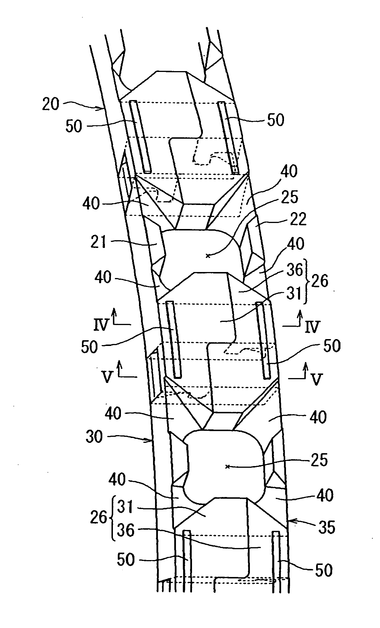
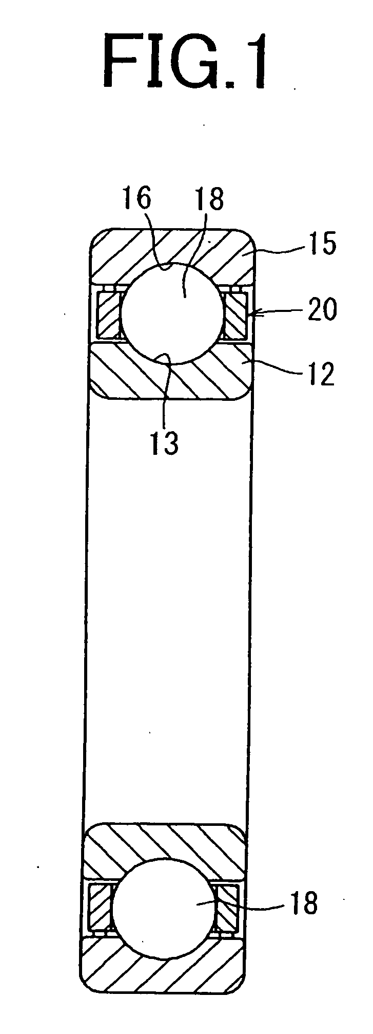
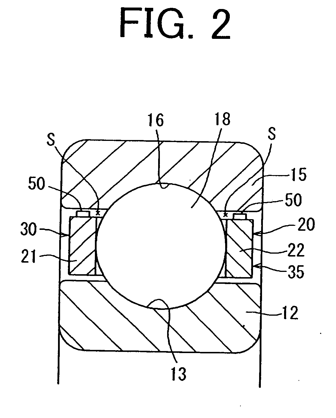
[0022]The first embodiment of the invention will be described with reference to FIGS. 1 to 6. FIG. 1 is a sectional view showing a deep-grooved ball bearing that incorporates a cage for a rolling bearing according to the first embodiment of the invention. FIG. 2 is a sectional view showing on an enlarged scale the assembled state of an inner ring, an outer ring, and a rolling element of the deep-grooved ball bearing and the cage. FIG. 3 is a perspective view showing part of the cage on an enlarged scale. FIG. 4 is a sectional view taken along a line IV-IV of FIG. 3. FIG. 5 is a sectional view taken along a line V-V of FIG. 3. FIG. 6 is a sectional view showing oil grooves recessed in outer diameter faces of a first body portion and a second body portion.
[0023]As shown in FIGS. 1 and 2, in the first embodiment of the invention exemplifying a case where the rolling bearing is the deep-grooved ball bearing, a plurality of balls 18 are used as rolling elements and arranged between a tra...
PUM
 Abstract
Description
Claims
Application Information