Load test system

a load test and load technology, applied in the field of load testing devices, can solve the problems of large fines, burden of such testing on users, and inability to ensure that all produced lifting devices meet the regulatory standards

Active Publication Date: 2009-03-12
TANDEMLOC
View PDF7 Cites 12 Cited by
  • Summary
  • Abstract
  • Description
  • Claims
  • Application Information

AI Technical Summary

Benefits of technology

[0009]A hardened monitoring and control station may also be provided separate from the rigid structure, and may be enclosed and hardened to protect a user conducting the test in the event of catastrophic failure and debris resulting from failure of a test lift device during a test. Recording devices and display devices may also be located in the monitoring and control station to record data picked up by the load sensors resulting from the test, as well as to visually record the test through use of the camera, and to display the data and images.

Problems solved by technology

On the other hand, regulatory agencies such as OSHA in the United States, often demand testing and the burden of such testing often falls on the user to provide certification that the lifting device has been load tested prior to use.
Failure to comply with testing can result in large fines being levied on the user.
This practice does not guarantee that all produced lift devices satisfy the regulatory standards, and it is preferable that every lift device produced be load tested before delivery to a customer.
Unfortunately, such a task has to date been prohibitably expensive.

Method used


Image

  • Load test system
  • Load test system
  • Load test system

Examples


Embodiment Construction

[0024]In one respect, embodiments consistent with the invention may capitalize on a load test system that can test a wide variety of shapes and sizes, based in part upon a rolling beam feature, and the size of the load test system which provides numerous anchoring locations so that the test lift device can be properly evaluated and tested under conditions substantially approximating actual field conditions.

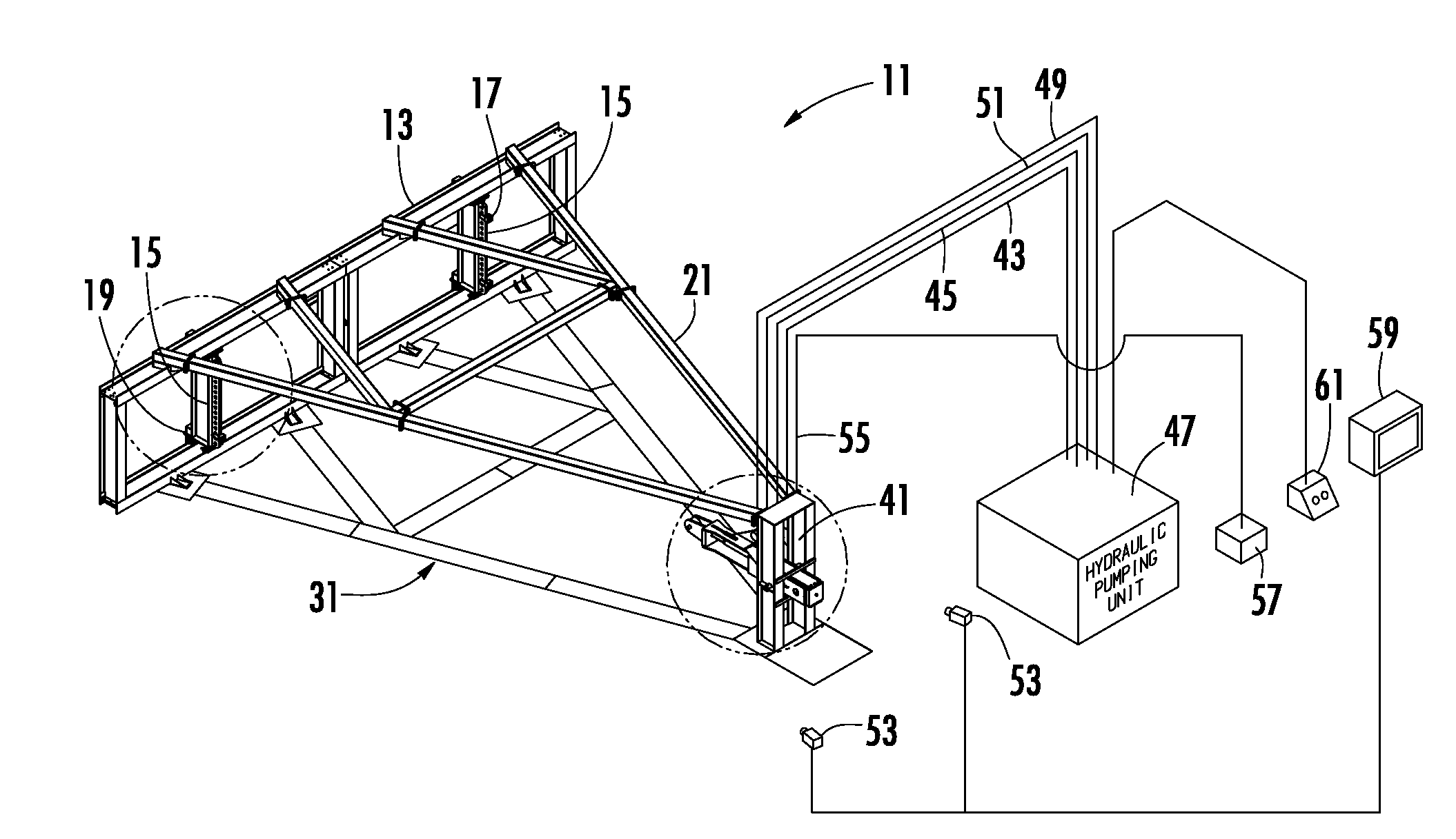
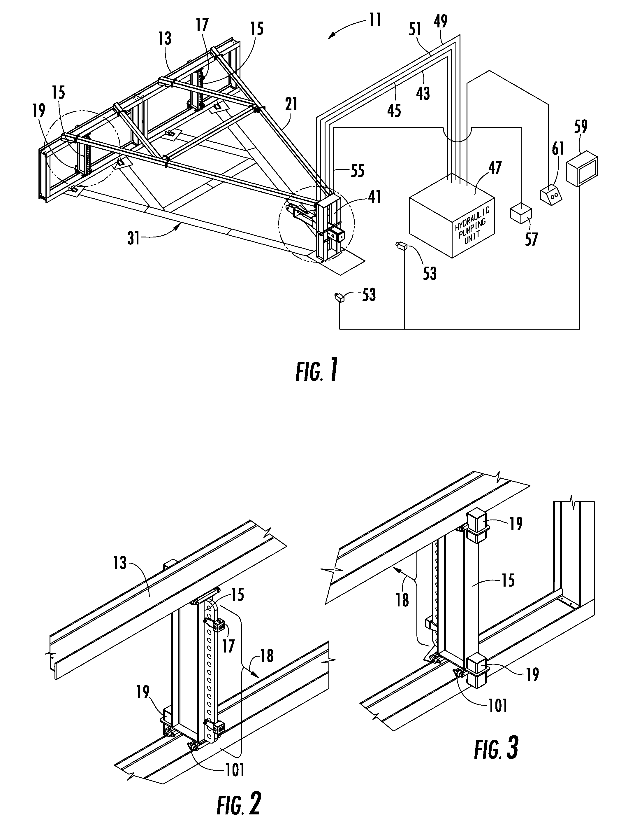
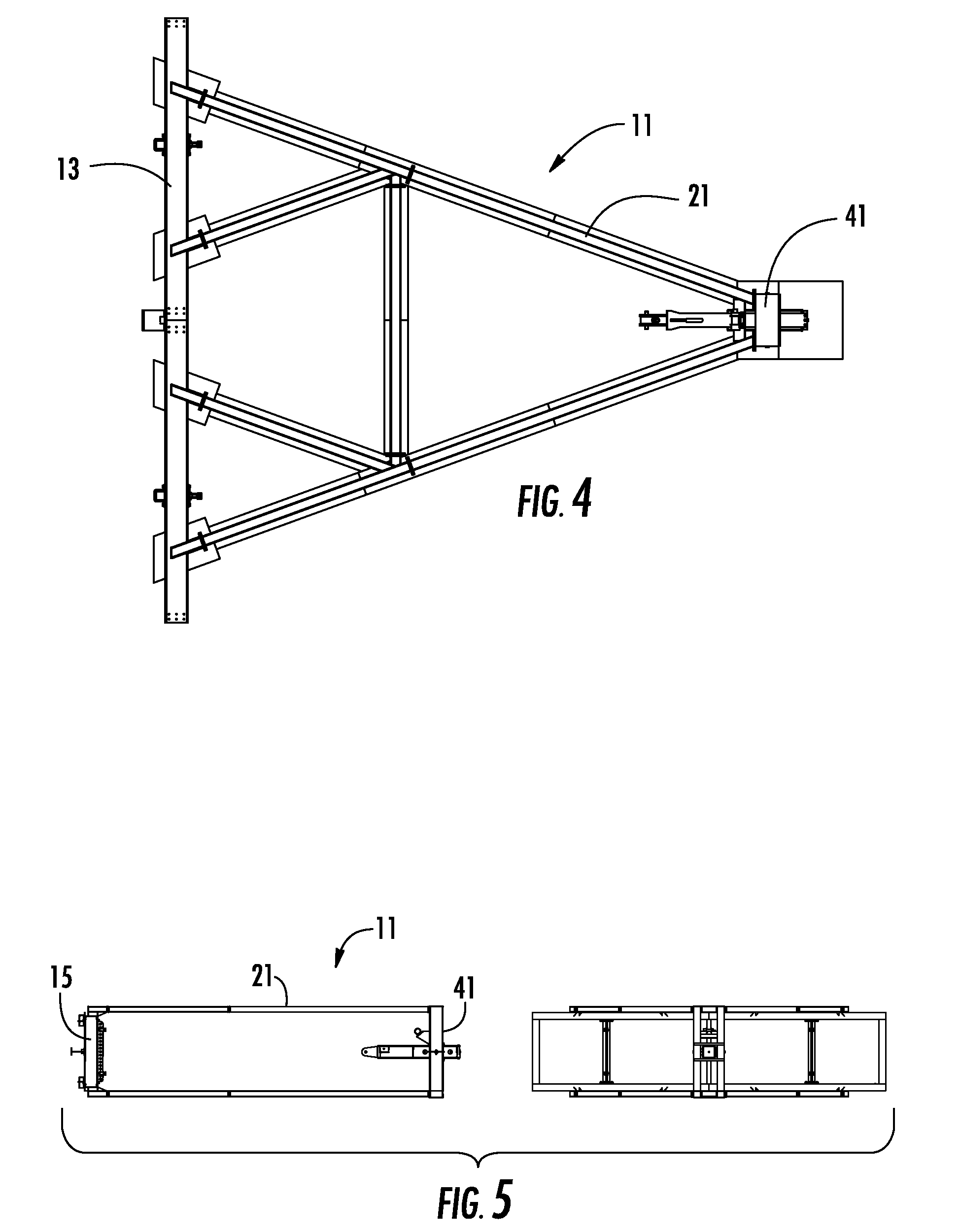
[0025]FIG. 1 illustrates in perspective view a load test system 11 in accordance with the invention, with some of the components thereof not shown for the sake of clarity. A test bed frame 13 extends horizontally along a first axis and includes rolling beams 15 which typically have a number of connection points spaced equally along the vertical axis of the beams 15 for attachment of pad eyes 17. The beams 15 can roll back and forth along the test bed frame 13 as more clearly shown in FIGS. 2 and 3 through the means of rollers 101. Securing tabs 19 on the rear side of the test bed ...


PUM

PropertyMeasurementUnit
hydraulic pressureaaaaaaaaaa
hydraulic pressure meteraaaaaaaaaa
sizesaaaaaaaaaa

Abstract

A load test system includes a test bed frame which extends horizontally along a first axis and includes two rolling beams moveably mounted securely in the test bed frame for being moved to desired position. The rolling beams have plural attachment locations for attaching a test lift device. A hydraulic power station is located spaced perpendicular from the test bed frame along a second axis and includes a hydraulic cylinder with a line connected to the hydraulic cylinder at one end, which is connectable to a test device at another end for applying a load when the test device is attached to the test bed. Beam members connect the hydraulic power station and the test bed frame to form a rigid structure.

Description

CROSS REFERENCE TO RELATED APPLICATIONS[0001]This application is related to U.S. Provisional Patent Application Ser. No. 60 / 970,546 for Load Test System filed Sep. 7, 2007, the disclosure of which is specifically incorporated in its entirety by reference herein. Applicants hereby expressly claim priority to the filing date of Sep. 7, 2007 of Application Ser. No. 60 / 970,546.FIELD OF THE INVENTION[0002]This invention relates to a system for load testing devices such as for use with “below-the-hook lifting devices.” More particularly, the invention relates to such a test system which provides a standardized methodology with recorded results which can be used to ensure compliance with regulations from relevant government agencies.BACKGROUND OF THE INVENTION[0003]A “below-the-hook lifting device” is a sling, hook, magnet, or vacuum device, beam or fabricated structural device that is suspended from the hook of an overhead crane or hoisting device, and used to lift an object. They are als...

Claims


Application Information

Patent Timeline
Patent Type & Authority Applications(United States)
IPC IPC(8): G01N3/02
CPCG01N3/02G01N2203/0048G01N2033/0078G01N3/10
Inventor DIMARTINO, SR., JOHN MICHAELDIMARTINO, WILLIAM DAVID
Owner TANDEMLOC
Why Eureka
Try Eureka