Servo drive system and continuous working system of press machine

a technology of servo drive and press machine, which is applied in the direction of gearing, forging presses, forging/pressing/hammering apparatus, etc., can solve the problems of complex noise generation principles, small noise, and noise in punching work, so as to reduce the peak electricity of the control circuit, enhance the operation efficiency, and reduce the effect of nois

Inactive Publication Date: 2009-03-12
AMADA CO LTD
View PDF11 Cites 3 Cited by
  • Summary
  • Abstract
  • Description
  • Claims
  • Application Information

AI Technical Summary

Benefits of technology

[0021]A third aspect of the present invention provides the servo drive system according to the first or the second aspect, wherein the pair of servo motors use a torque based on speed-torque characteristics of a motor, and if a load is received from a work during a lowering operation of the ram to generate necessary ram pressure without utilizing inertia of a mechanism, speeds of both the servo motors are reduced according to the load, thereby reducing the lowering speed of the ram.
[0037]According to the servo drive system of the thirteenth and the fourteenth aspects, the servo motor has the control power driver, the power driver being provided at its front stage with the reactor which suppresses peak current by cutting off high frequency current component, and the capacitor which supplies electric energy which becomes short due to suppression of the peak current. Therefore, it is possible to decrease a noise and to enhance the operation efficiency at the same time by automatically increasing and decreasing the punching speed according to a load, and it is possible to reduce a peak electricity of a control circuit for the servo motor.

Problems solved by technology

In punching working of a press machine such as a punch press, since extremely large noise is generated during the working, it is required to decrease this kind of noise as small as possible.
Principles of generation of noise in the punching working are complicated, and reasons of generation of noise are varied depending upon various conditions such as the material of the work, the plate thickness, and the like.
However, it is known that the noise is large when the punching speed by driving of a ram is fast, the noise becomes smaller when the punching speed becomes slower, and when the punching speed is constant, the noise is small when the load is light, and as the load becomes heavier, the noise becomes larger.
However, the conventional electric punch press generates a torque necessary for working by using a mechanism such as a toggle and a flywheel.
Therefore, the inertia caused by this mechanism delays the reciprocating motion of the ram.
In addition, an operation shaft which vertically moves the ram and a main shaft of a servo motor is driven through a power transmission mechanism such as a gear, and a loss or a delay is generated by the power transmission mechanism.
Even if the speed of the servo motor is controlled, the driving speed of the ram can not follow the speed of the servo motor easily, and therefore the conventional technique is not suitable for controlling the speed of the ram.
For this reason, the conventional technique has problems that since the punching speed is set substantially at a constant value irrespective of the weight of the load, if the punching speed is set lower to decrease the noise, the operation efficiency is largely deteriorated, and if the punching speed is set higher to enhance the operation efficiency, a large noise is generated and thus, reduction of noise and enhancement of operation efficiency can not be satisfied at the same time.
Therefore, complicated control systems such as high-speed processing hardware and software are required.
In the conventional hydraulic punch press, however, since the ram is reciprocated using a hydraulic pressure and a switching valve, response speed is inferior to that of the electric control, and a response delay to the control command is generated and thus, the conventional hydraulic punch press is not suitable for speedup of the ram.
Further, the conventional technique has problems that since the punching speed is set substantially at a constant value irrespective of the weight of the load, if the punching speed is set lower to decrease the noise, the operation efficiency is largely deteriorated, and if the punching speed is set higher to enhance the operation efficiency, a large noise is generated and thus, reduction of noise and enhancement of operation efficiency can not be satisfied at the same time.

Method used


Image

  • Servo drive system and continuous working system of press machine
  • Servo drive system and continuous working system of press machine
  • Servo drive system and continuous working system of press machine

Examples


Embodiment Construction

[0058]Embodiments of the present invention will be explained in detail with reference to the accompanying drawings.

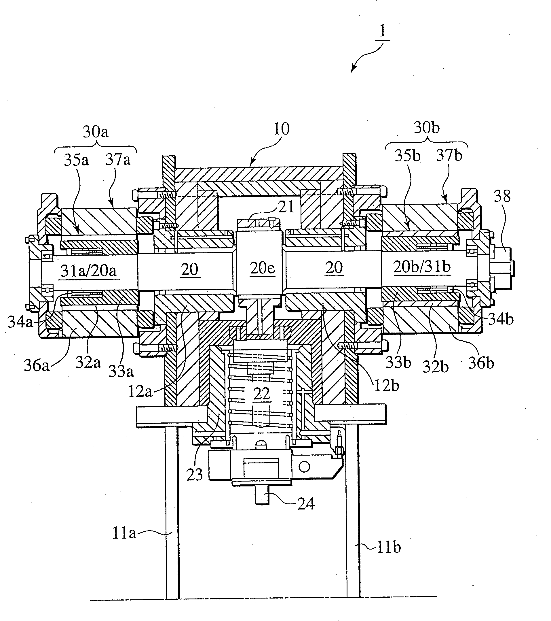
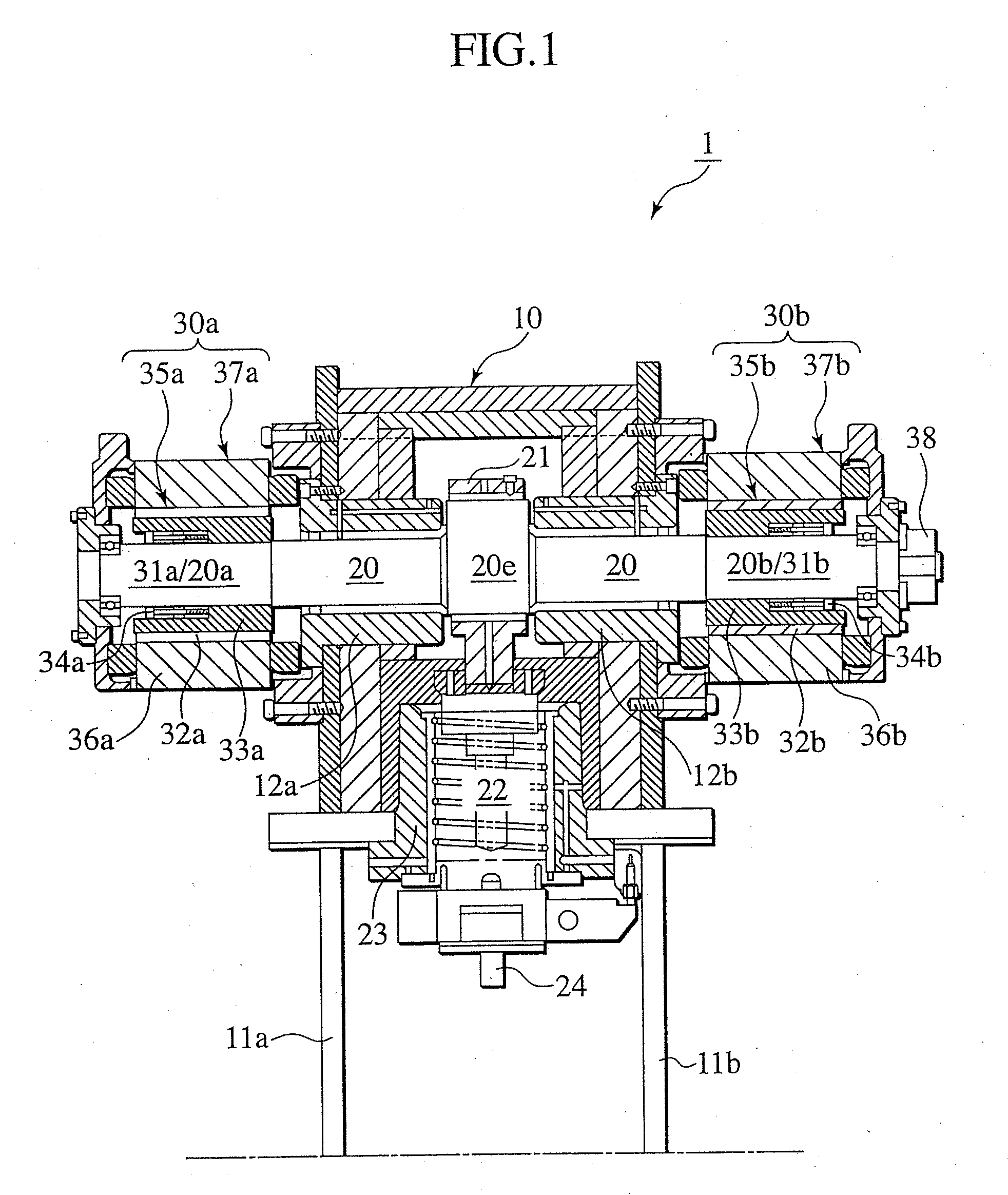
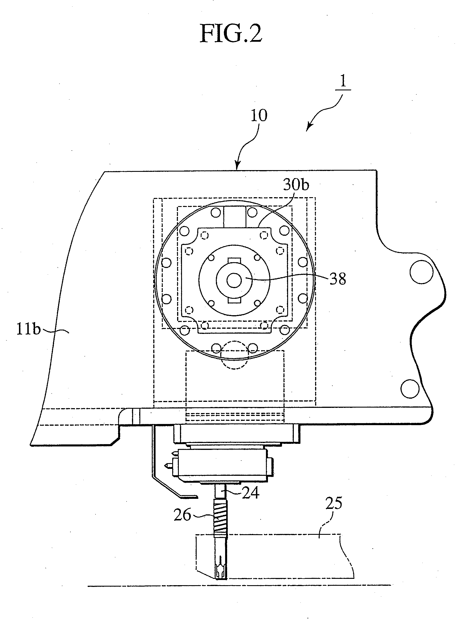
[0059]FIG. 1 is a vertical sectional view of an essential portion showing an embodiment of a servo drive system (continuous working system) of a press machine according to the present invention, and FIG. 2 is a right side view thereof. The servo drive system (continuous working system) 1 of the press machine is applied to a turret punch press 10.

[0060]The turret punch press 10 has an eccentric shaft 20 which is pivotally supported by bearings 12a and 12b provided on frames 11a and 11b which stand in parallel to each other. The eccentric shaft 20 has an eccentric shaft portion 20e located substantially at a central portion between the frames 11a and 11b. A ram 22 is mounted on the eccentric shaft portion 20e through a connecting rod 21. If the eccentric shaft 20 rotates or turns, the ram 22 is vertically moved through the connecting rod 21 along a ram guide 23, and a str...


PUM


Abstract

A servo drive system of a press machine includes a ram, an operation shaft which vertically moves the ram, and a servo motor which operates as a power source of the ram and which generates ram pressure using a torque based on at least one speed-torque characteristic of the servo motor. The operation shaft is directly driven using the servo motor. The at least one speed-torque characteristic of the servo motor is set in a manner such that a motor torque of the servo motor at which a capacity of electric energy supplied by a servo amplifier is determined becomes the motor torque at which an optimal punching pattern of the ram is generated from a light load to a heavy load according to a type of workpiece to be worked by the press machine.

Description

CROSS REFERENCE TO RELATED APPLICATION[0001]This application is a continuation of pending U.S. patent application Ser. No. 10 / 517,317, filed Dec. 17, 2004, which is a National Stage of PCT / JP03 / 07675, filed Jun. 17, 2003, the disclosures of which are expressly incorporated herein by reference in its entirety.TECHNICAL FIELD[0002]The present invention relates to a servo drive system of a press machine applied to a turret punch press, and more particularly, to a continuous working system of a press machine applied to a turret punch press.BACKGROUND ART[0003]Conventionally, there are electric punch presses using a servo motor as a driving source of a ram. In punching working of a press machine such as a punch press, since extremely large noise is generated during the working, it is required to decrease this kind of noise as small as possible.[0004]Principles of generation of noise in the punching working are complicated, and reasons of generation of noise are varied depending upon vari...

Claims


Application Information

Patent Timeline
Patent Type & Authority Applications(United States)
IPC IPC(8): B26D5/16B21D28/36B30B1/26B30B15/14B30B15/18H02P6/08
CPCB30B1/266B30B15/148Y10T74/19698Y10T74/2036Y10T74/18056Y10T74/19056Y10T74/18248Y10T74/20341Y10T83/8843Y10T83/8844Y10T83/8726B30B15/14B30B1/00
Inventor NAITO, KINSHIROSEKIYAMA, TOKUZOOTAKE, TOSHIAKIKURIYAMA, HARUHIKO
Owner AMADA CO LTD
Why Eureka
Try Eureka