Automated configuration of a power monitoring system using hierarchical context

a technology of automatic configuration and power monitoring system, applied in the field of utility systems, can solve the problems of service providers having to devote a substantial amount of time and not meet the requirements of the power monitoring system, and achieve the effects of reducing or eliminating the need for manual configuration, increasing short-term and long-term operational effectiveness, and saving tim

Active Publication Date: 2009-03-12
SQUARE D CO
View PDF6 Cites 56 Cited by
  • Summary
  • Abstract
  • Description
  • Claims
  • Application Information

AI Technical Summary

Benefits of technology

[0007]Using the knowledge of the location of a monitoring device within the context of a hierarchically organized power monitoring system can provide many benefits that are currently unavailable in existing power monitoring systems. While minimizing or in many cases eliminating user intervention, aspects of the present invention efficiently and appropriately configures and verifies a power monitoring system based upon each monitoring device's location within the monitoring system. Aspects of the present invention also increase the short-term and long-term operational effectiveness of both discrete monitoring devices and the power monitoring system as a whole. Furthermore, aspects of the present invention automatically detect and notify the end-user of erroneous configurations, potential safety considerations, misapplications of monitoring devices (with recommendations), monitoring device malfunctions, and other issues that may otherwise go unnoticed.
[0008]Providing end-users with a more automated “plug-and-play” method of configuring and verifying the power monitoring system can save time, reduce costs, and improve safety. Aspects disclosed herein can lengthen the time between hardware design cycles and improve customer satisfaction.

Problems solved by technology

Typically, the user configures the monitoring devices with generic templates, which may not meet the requirements of the power monitoring system.
Presently, appropriately installing, configuring, and commissioning the power monitoring devices and software often require more than one day.
Furthermore, in every case, service providers have to devote a substantial amount of time to analyze the monitoring system and the application to confirm proper configuration.

Method used


Image

  • Automated configuration of a power monitoring system using hierarchical context
  • Automated configuration of a power monitoring system using hierarchical context
  • Automated configuration of a power monitoring system using hierarchical context

Examples


Embodiment Construction

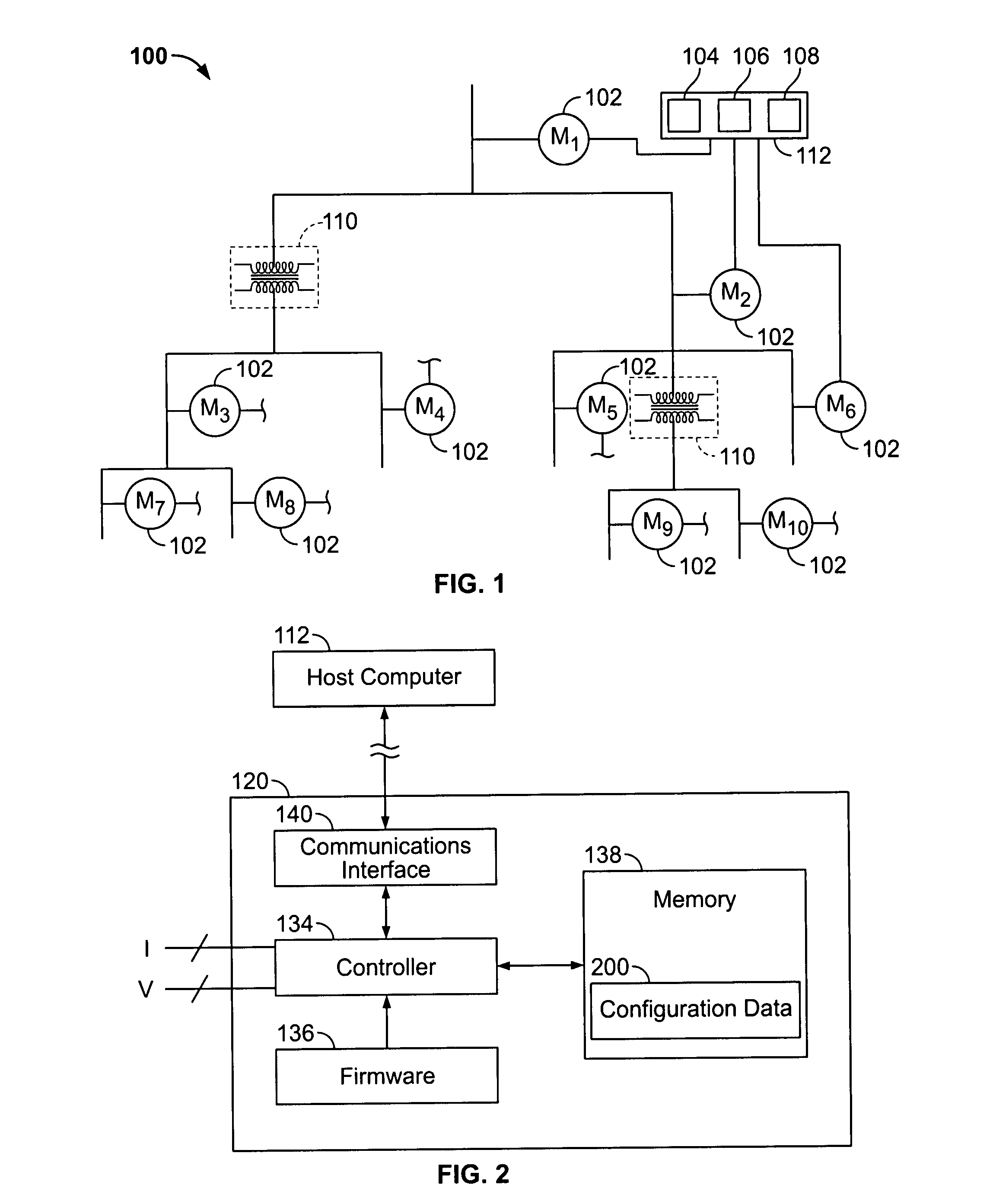
[0024]Turning now to FIG. 1, a power monitoring system 100 having two or more monitoring devices 102 (labeled M) providing characterized data from each discrete location. As used herein, a monitoring device refers to any system element or apparatus with the ability to sample, collect, and / or measure one or more electrical characteristics or operational parameters of a utility system. The power monitoring system 100 is part of an electrical system that includes the monitoring devices 102. By “power” in the term power monitoring system, it is meant to include power, voltage, current, frequency, or other electrical characteristics that can be used to determine and characterize the electrical system hierarchy. In some aspects, the data from each monitoring device 102 is communicated to an automated data alignment module 104, an automated hierarchy classification module 106 and an automated configuration module 108. These systems can be implemented as algorithms on a computer-readable me...


PUM


Abstract

Methods of automatically configuring a power monitoring system based upon the locations of the monitoring devices in a hierarchy representing the spatial interrelationships of the monitoring devices. The power monitoring system includes a host computer communicatively coupled to a plurality of monitoring devices arranged in a hierarchy in an electrical system. Software on the host computer may execute any or all of an alarm aggregation algorithm for aggregating multiple alarms based on device location; a feature distribution algorithm for enabling / disabling selected device features; an evaluation algorithm for evaluating device applications; a device check algorithm for detecting flawed data; a custom configuration algorithm for customized configuration of thresholds on device-by-device basis; a host computer configuration algorithm for configuring the host computer; a redundancy algorithm for verifying an electrical event; an alarm configuration algorithm for configuring device thresholds; and a configuration error checking algorithm for detecting nomenclature issues.

Description

FIELD OF THE INVENTION[0001]The present invention relates generally to utility systems, and, in particular, to a method for automatically configuring a power monitoring system based upon the hierarchical relationship of the monitoring devices with respect to the power monitoring system, which is part of an electrical system.BACKGROUND OF THE INVENTION[0002]Configuring a power monitoring system requires the user to setup each monitoring device (and its associated software) on an discrete basis, a task that necessitates an understanding of each monitoring device's capabilities. The user must also evaluate each monitoring device with respect to its location in a hierarchically organized power monitoring system. Furthermore, the user must understand each monitoring device's application to properly configure alarming thresholds, data logging requirements, etc. Finally, the user must configure the power monitoring system software to accommodate each specific device.[0003]Typically, the us...

Claims


Application Information

Patent Timeline
Patent Type & Authority Applications(United States)
IPC IPC(8): G08B21/00
CPCG01D4/004G01R19/2513Y02B90/242Y02B90/245Y04S20/48Y04S20/322Y04S20/40Y04S20/42Y02B90/246G01D2204/14G01D2204/45G01D2204/47Y02B90/20Y04S20/30
Inventor BICKEL, JON ANDREWCARTER, RONALD W.CURTIS, LARRY E.
Owner SQUARE D CO
Why Eureka
Try Eureka