Packet forwarding apparatus suitable for forwarding extended frame

Inactive Publication Date: 2009-03-12
HITACHI LTD
View PDF6 Cites 222 Cited by
  • Summary
  • Abstract
  • Description
  • Claims
  • Application Information

AI Technical Summary

Benefits of technology

[0016]Further, by applying the packet forwarding apparatus according to the invention as a connection node between heterogeneous networks different in frame format or MTU, it is possible to efficiently forward communication frames without adjusting

Problems solved by technology

In a wide area network composed of communication nodes supplied by a plurality of vendors different in standard, therefore, communication has to be performed with jumbo frames having the minimum size in all communication paths and it b

Method used


Image

  • Packet forwarding apparatus suitable for forwarding extended frame
  • Packet forwarding apparatus suitable for forwarding extended frame
  • Packet forwarding apparatus suitable for forwarding extended frame

Examples


Embodiment Construction

[0036]Hereinafter, an embodiment of the present invention will be described in detail with reference to the accompanying drawings.

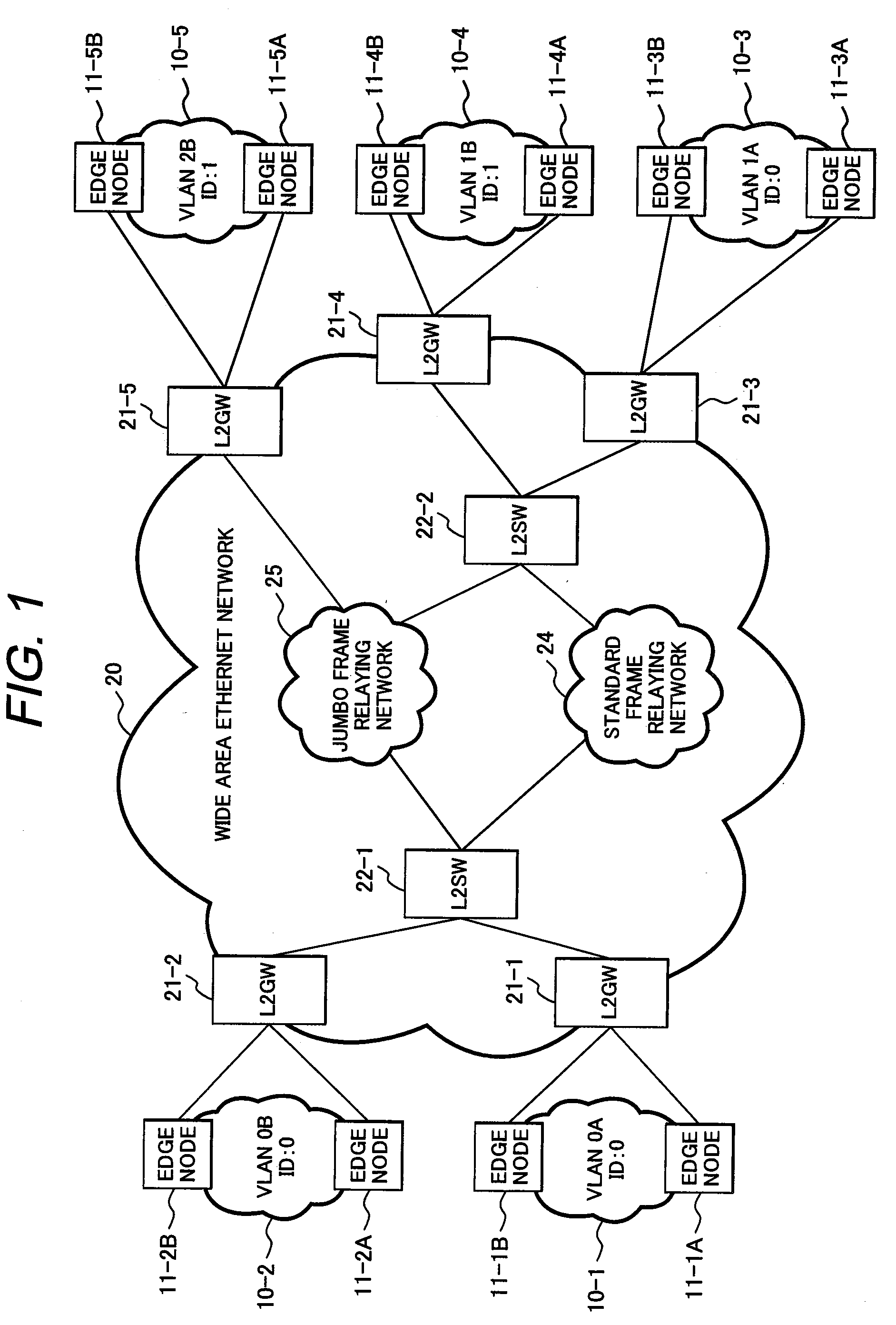
[0037]FIG. 1 shows an example of a network configuration to which a packet forwarding apparatus (layer 2 switch: L2SW) according to the invention is applied.

[0038]A wide area Ethernet network 20 is composed of a standard frame relaying network 24, a jumbo frame relaying network 25, a plurality of layer 2 gateways (L2GW) 21 (21-1 to 21-5), and a plurality of layer 2 switches (L2SW) 22 (22-1, 22-2). Numeral 10 (10-1 to 10-5) indicates a VLAN for accommodating a plurality of user terminals or servers not shown in FIG. 1.

[0039]Each VLAN 10 is connected through at least one edge node 11 (11-1A to 11-5B) to one of the L2GWs 21 which is a connection point of the wide area Ethernet network 20. In the example of FIG. 1, each VLAN 10 is connected through two edge nodes 11 to one of L2GWs, and each L2GW 21 is connected via an L2SW 22 to the standard frame relaying n...


PUM


Abstract

A packet forwarding apparatus (L2SW) having a frame segmentation function of converting a extended Ethernet frame such as a MAC-in-MAC frame into a plurality of fragment frames when a payload length of the received frame exceeds a standard MTU size communicable in an Ethernet network to be a forwarding destination, by segmenting the received frame into a plurality of data blocks having a size not longer than the MTU size, and a frame assembling function of restoring an original extended frame from a series of fragment frames received from the Ethernet network.

Description

CLAIM OF PRIORITY[0001]The present application claims priority from Japanese patent application serial No. 2007-231204, filed on Sep. 6, 2007, the content of which is hereby incorporated by reference into this application.BACKGROUND OF THE INVENTION[0002]1. Field of the Invention[0003]The present invention relates to a packet forwarding apparatus, and more particularly, to a packet forwarding apparatus applicable to a wide area Ethernet network in which extended Ethernet (registered trademark) frames such as MAC-in-MAC frames are forwarded.[0004]2. Related Art[0005]With the spread of constructing intranets utilizing the Internet technology, a wide area network (WAN) for connecting a local area network (LAN) with another LAN has become widespread. The WAN started services at relatively high cost due to the use of low-speed telephone lines and dedicated lines. However, with the spread of high-speed XDSL and optical links, the WAN became able to provide services at low cost.[0006]At th...

Claims


Application Information

Patent Timeline
IPC IPC(8): H04L12/56H04L12/46H04L47/43
CPCH04L12/4641H04L49/3009H04L47/36
Inventor NAGAI, MINORUMIYATA, HIROAKI
Owner HITACHI LTD
Why Eureka
Try Eureka