Packet relay device

a relay device and relay technology, applied in data switching networks, multiplex communication, digital transmission, etc., can solve the problems of loss of multicast communications merit, heavy load on the routing process of each relay device, and management burden, and achieve efficient administration and efficient forwarding of communication packets

Inactive Publication Date: 2011-02-22
FUJITSU LTD
View PDF31 Cites 10 Cited by
  • Summary
  • Abstract
  • Description
  • Claims
  • Application Information

AI Technical Summary

Benefits of technology

[0013]It is an object of the present invention to provide a packet relay device that efficiently forwards communication packets transmitted from a plurality of terminals connected to a network.
[0025]With this scheme, according to the present invention, it is feasible to realize the intra-group multicast in a closed network where the respective terminals are grouped and to eliminate the multicast packet sent from outside of the group.
[0029]With this scheme, the packet relay device according to the present invention automatically takes synchronization of the address information etc of the terminal group in the network where the plurality of terminals exists, whereby the addresses are automatically managed and automatically assigned so as not to cause any overlap, and consequently the network can be efficiently administered.
[0030]According to the present invention, it is possible to actualize the packet relay device capable of efficiently forwarding the communication packets from the plurality of terminals connected to the network.

Problems solved by technology

This scheme, as well as causing a rise in load on management of the multicast addresses, leads to a heavy load on the routing process in each relay device.
Further, the method 1 needs to manage, because of translating the multicast packet into the unicast packet and forwarding the packet, for realizing the many-to-many communications, all pieces of address information about the destination terminal in the communications, to which the packet should be forwarded, resulting in a loss of merit of the multicast communications.
Namely, those methods are incapable of improving scalability as the number of the terminals connected to the network rises and actualizing forwarding the multicast packet / broadcast packet on a predetermined management basis (group-by-group basis).

Method used


Image

  • Packet relay device
  • Packet relay device
  • Packet relay device

Examples


first embodiment

Operation / Effect in First Embodiment

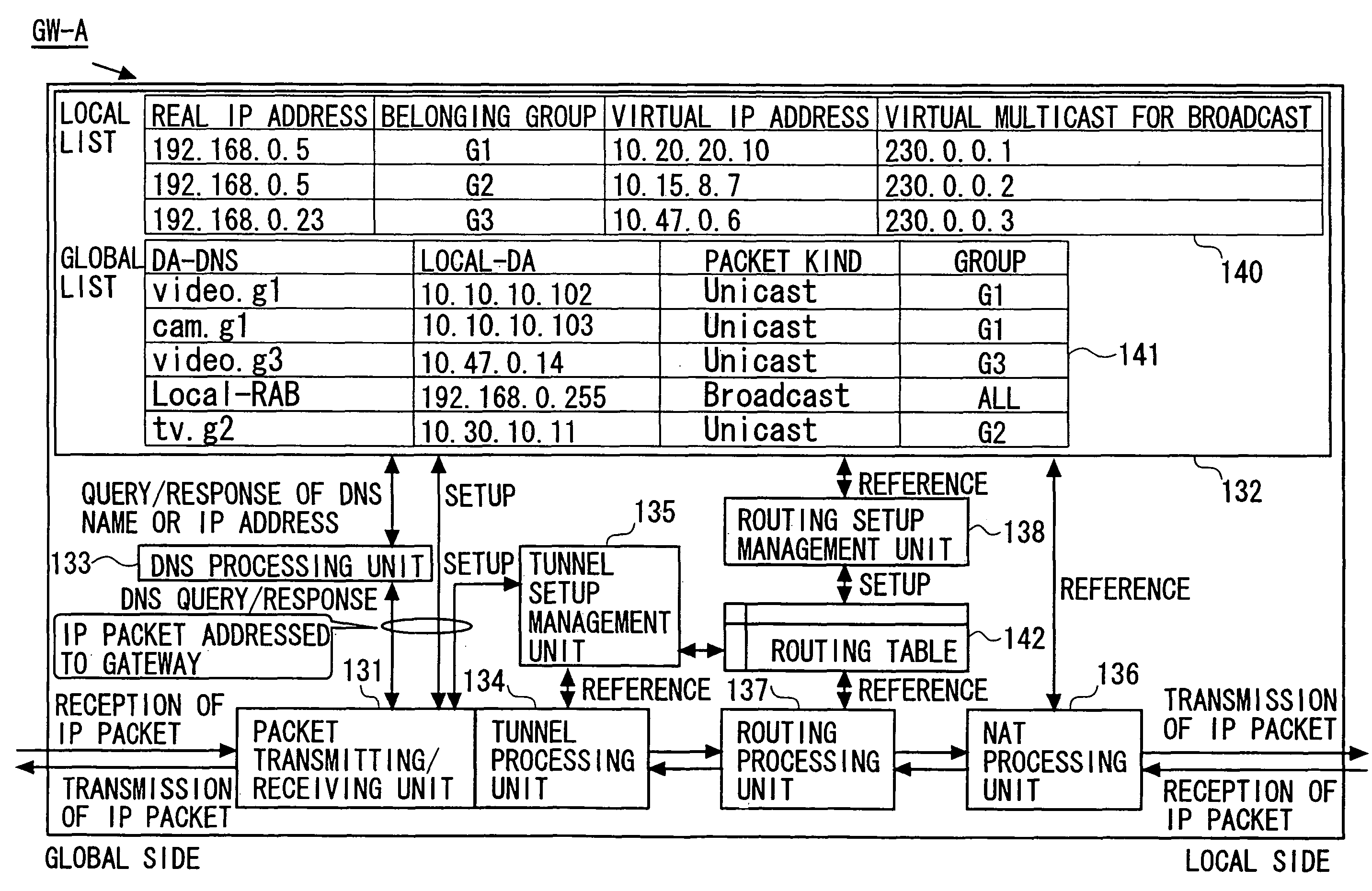
[0153]The gateway in the first embodiment forwards the broadcast packet transmitted by the terminal to all of the groups to which the terminal 101 belongs. In this gateway, on the occasion of forwarding the packet, the NAT processing unit 136 executes the NAT (Network Address Translation) process.

[0154]To be specific, the present gateway translates the source address and the destination address (the broadcast addresses) of the broadcast packet sent from the terminal 101 into the virtual IP address and the virtual multicast address that are managed for every forwarding destination group, and transmits this address-translated packet. Further, in the case of receiving the address-translated packet, the gateway translates the destination address of the packet into the real broadcast address associated with the virtual multicast address set in the received packet, and forwards this packet.

[0155]The gateways in the first embodiment manage, it may be suf...

second embodiment

Operation / Effect in Second Embodiment

[0195]The gateway in the second embodiment forwards the multicast packet transmitted by the terminal 101 to the terminal group of the terminals serving as the members of the group associated with the multicast address thereof.

[0196]In the present gateway, on the occasion of this forwarding, the NAT processing unit 136 executes the NAT process. The operation and the effect of the present gateway related to the NAT process are the same as those in the first embodiment.

[0197]Further, the NAT processing unit 136 of the present gateway, when receiving the multicast packet from the terminal 101, recognizes the group to which the multicast address belongs from this multicast address set in the multicast packet by referring to the global list 141 and the local list 140, and forwards the multicast packet to the terminal group belonging to this group.

[0198]This operation enables each of the terminals desiring for the transmission of the multicast packet to...

operational example

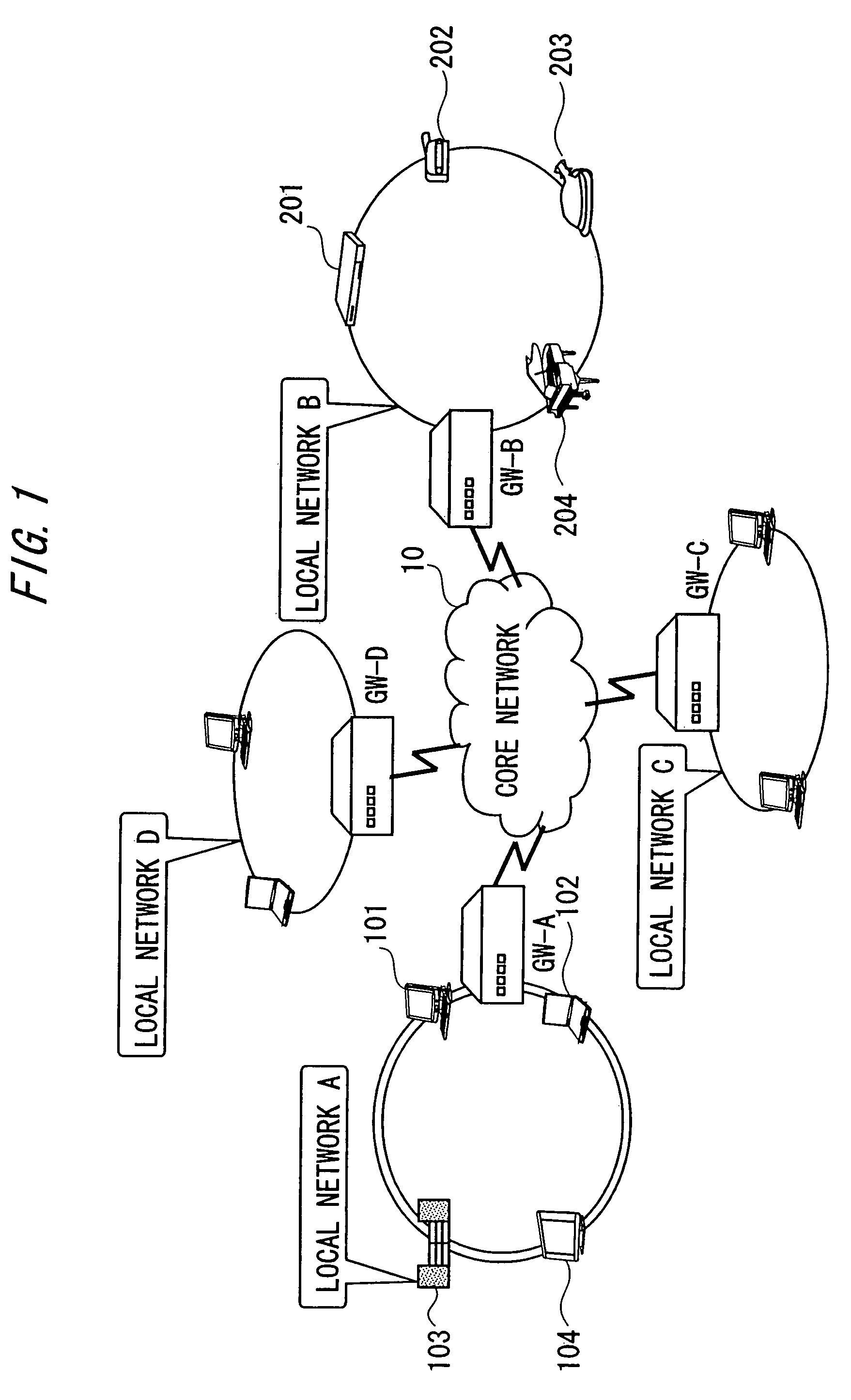
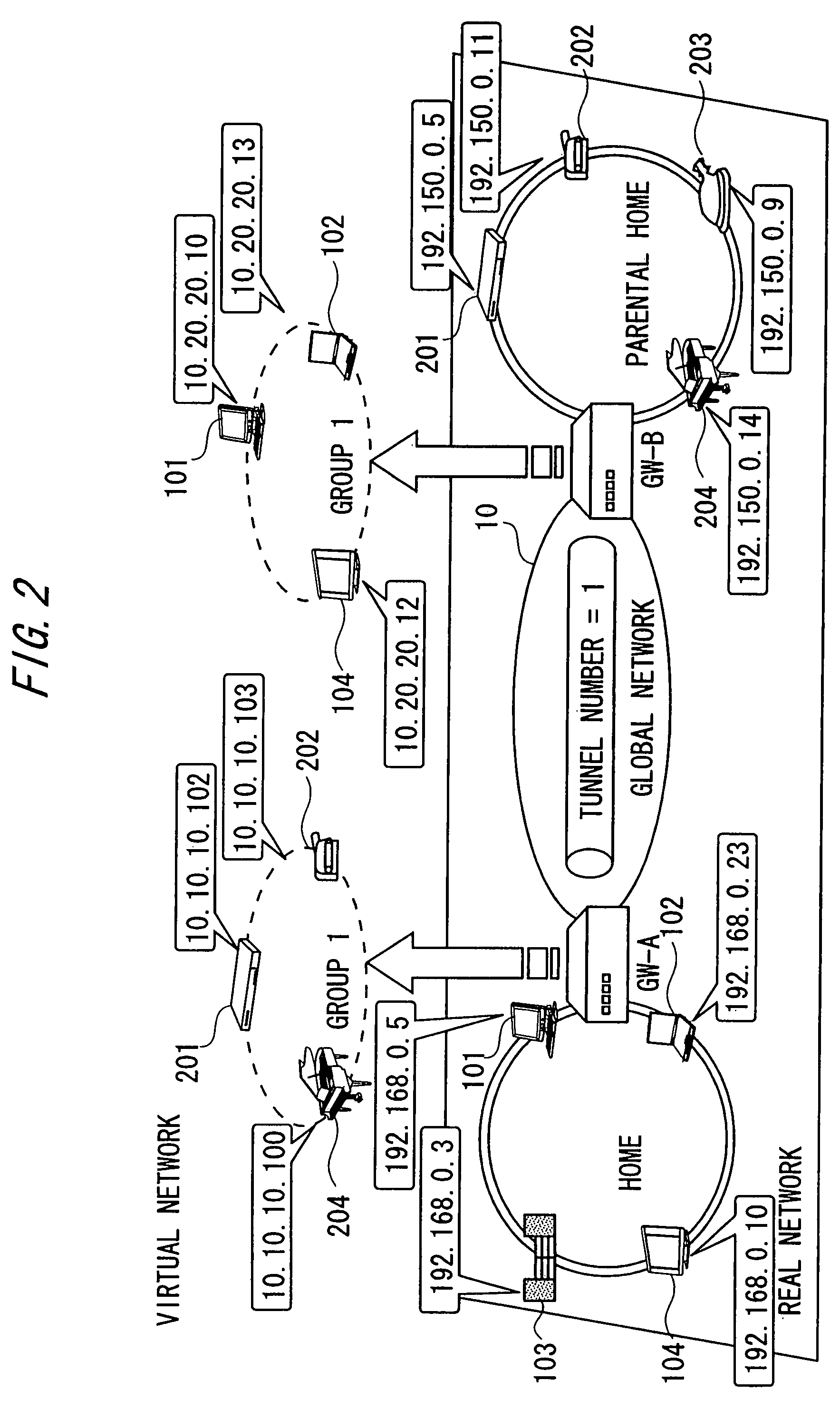
[0213]Next, an operational example of the gateway in the third embodiment will be described with reference to FIG. 16. FIG. 16 is a diagram showing a gateway-to-gateway synchronizing sequence in the third embodiment. Explained herein is, in a state of configuring the virtual network for the group 1 between the gateway GW-A and the gateway GW-B as illustrated in FIG. 2, an example where the terminal (e.g., a PDA) in the local network C managed by the gateway GW-C participates in the group 1.

[0214]In the state of configuring the virtual network for the group 1 between the gateway GW-A and the gateway GW-B, as stated earlier, the IP tunnel is generated between the gateway GW-A and the gateway GW-B (S1601).

[0215]In this state, at first, the gateway GW-C generates the IP tunnel with the gateway GW-B in order to participate in the group 1 (S1602). On the occasion of generating this IP tunnel, the gateway GW-C and the gateway GW-B mutually conduct gateway-to-gateway authentication and so o...


PUM


Abstract

Provided is a packet relay device for efficiently transferring a communication packet transmitted from a plurality of terminals connected with a network. The packet relay device is positioned in the network, in which a plurality of local networks are connected with each other through a global network, and at the boundary between the local network and the global network. The packet relay device comprises an acquisition unit for specifying the terminal of a transmission source from a broadcast packet transmitted by the terminal in the local network thereby to acquire group information on the group, to which the specified terminal belongs, a conversion unit for converting the broadcast packet into a virtual multicast packet corresponding to the group information acquired beforehand, a transfer unit for transferring the virtual multicast packet to another corresponding relay device, and a packet conversion unit for converting the virtual multicast packet into a corresponding real broadcast packet.

Description

CROSS-REFERENCE TO RELATED APPLICATION[0001]This is a continuation of Application PCT / JP2005 / 003788, filed on Mar. 4, 2005, now pending, the contents of which are herein wholly incorporated by reference.BACKGROUND OF THE INVENTION[0002]1. Field of the Present Invention[0003]The present invention relates to a packet relay device that provides a closed network on a group-by-group basis by virtually grouping a plurality of terminals connected to a network.[0004]2. Description of the Related Art[0005]IP (Internet Protocol) networks have spread over the recent years, and a variety of apparatuses are connected to the network. Along with this circumstance, such a configuration is considered that, e.g., electrical appliances each having a communication function are connected to the network and controlled from a personal computer (which will hereinafter be abbreviated to PC) connected to the same network.[0006]With the spread of this type of network, the number of the apparatuses connected t...

Claims


Application Information

Patent Timeline
Patent Type & Authority Patents(United States)
IPC IPC(8): H04L12/46H04L12/66H04L45/16
CPCH04L12/1836H04L12/2803H04L12/2836H04L12/4604H04L41/0893
Inventor YAMANE, SHINJI
Owner FUJITSU LTD
Why Eureka
Try Eureka