Floating self-centering connector

a self-centering, connector technology, applied in the direction of coupling device connection, manufacturing tools, instruments, etc., can solve the problems of shortened connector life, insufficient bending of the connector, and inability to ensure the alignment and eventual connection of the blind mate connector

Inactive Publication Date: 2009-03-12
MEZHINSKY VICTOR B
View PDF13 Cites 43 Cited by
  • Summary
  • Abstract
  • Description
  • Claims
  • Application Information

AI Technical Summary

Benefits of technology

[0007]Embodiments of the present invention substantially address the above identified needs and others. One object of the present invention is to provide a simple, self-centering floating connector and a floating mou...

Problems solved by technology

A reliable blind mate connector alignment and eventual connection are not guaranteed due to parts manufacturing tolerances and misalignment between the connector male and female components.
However, in some cases, the b...

Method used


Image

  • Floating self-centering connector
  • Floating self-centering connector
  • Floating self-centering connector

Examples


Embodiment Construction

[0020]Preferred embodiments of the present invention are illustrated in the FIGs., like numerals being used to refer to like and corresponding parts of the various drawings.

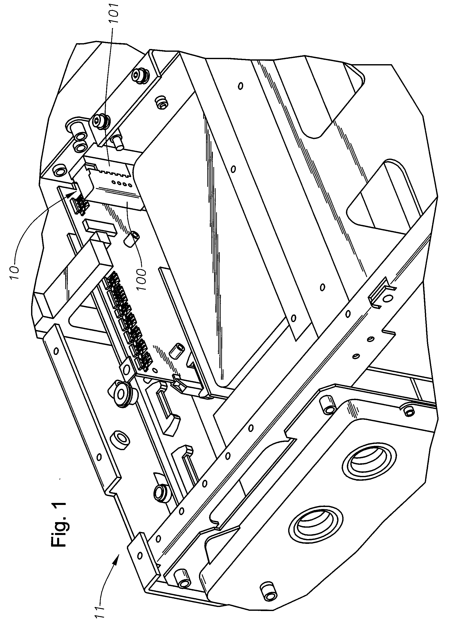
[0021]FIG. 1 depicts an embodiment of an engaged blind mate connector 10, in accordance with the present invention, within a laser assembly. The laser side portion 100 of the connector 10 (female in this example) has two alignment holes that cooperate and engage with the PCBA portion 101 of the connector 10. The PCBA portion 101 has two alignment pins adapted to cooperate with the alignment holes of the laser side portion 100, as is more clearly shown in FIGS. 2A and 2B, section A-A.

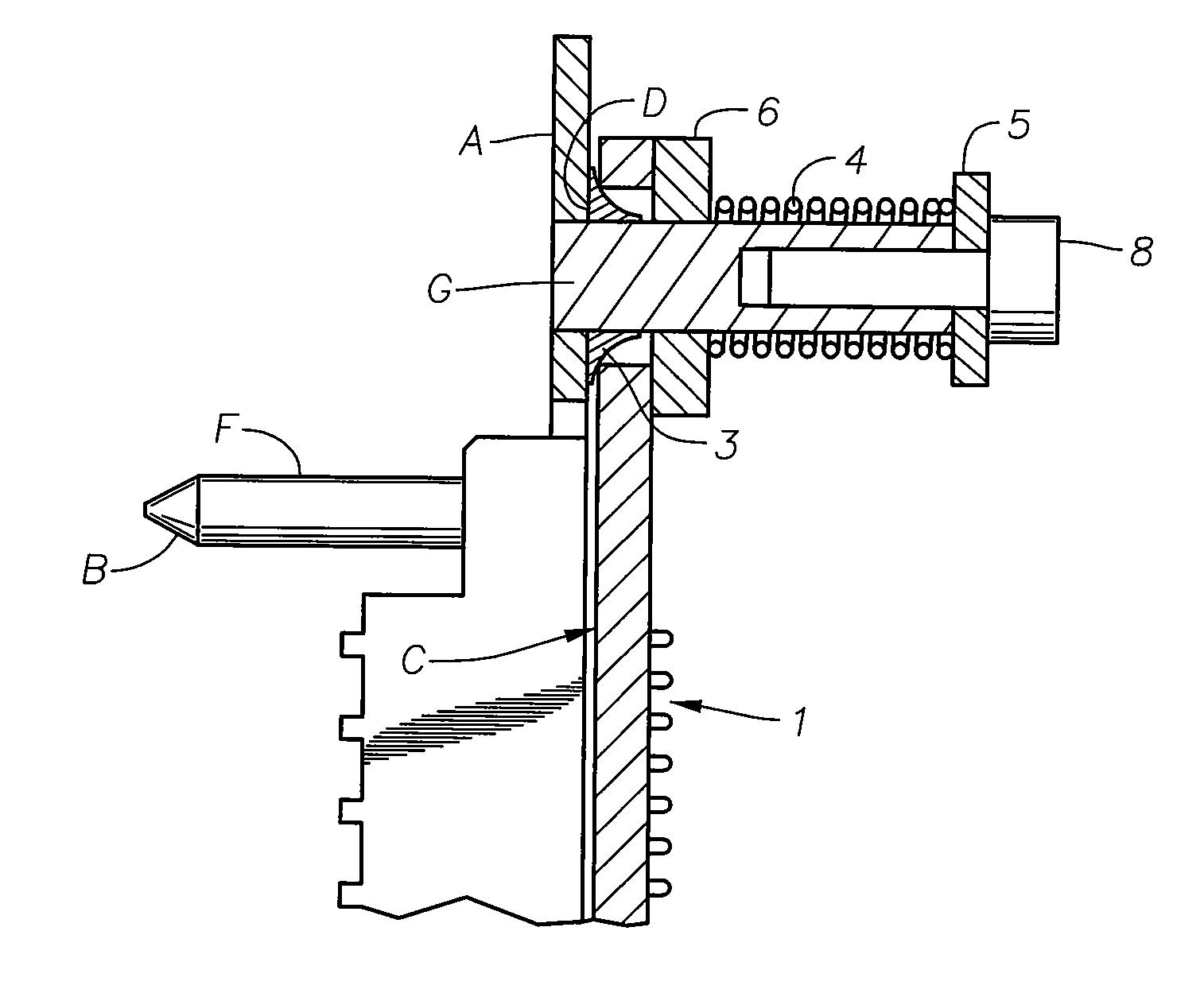
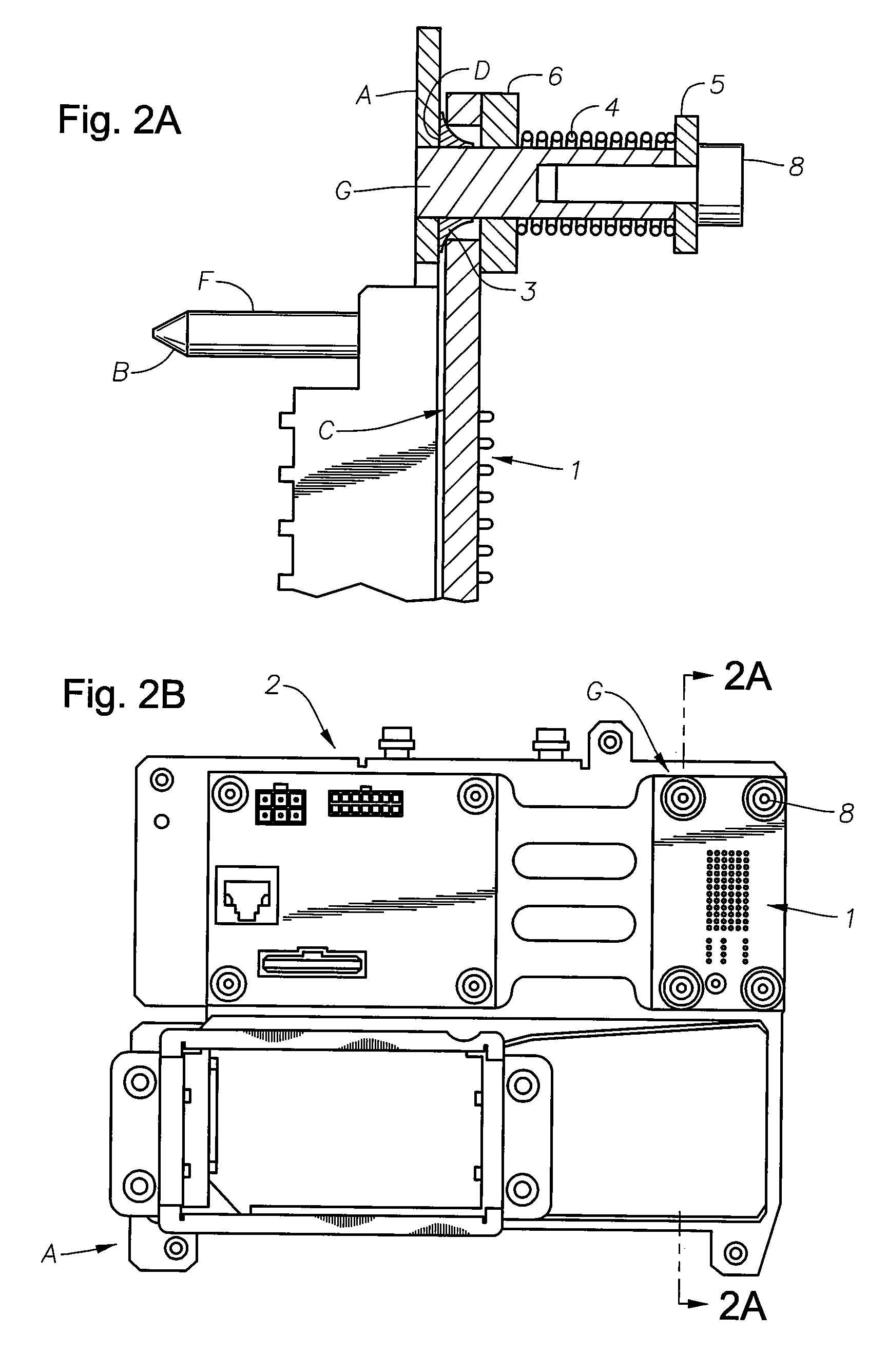
[0022]FIG. 2A provides a cross-section of a first sub-straight being a printed circuit board assembly mounted to a chassis using a free-floating compression fastener system in accordance with embodiment for the present invention. FIG. 2B provides a top-down view showing a printed circuit board assembly mounted to an equipment chassis ...


PUM

PropertyMeasurementUnit
Diameteraaaaaaaaaa

Abstract

A self-centering connection is provided. This self-centering connection includes a first substrate, a first connector assembly, a first number of alignment guides, a second substrate, a second connector assembly, a second number of alignment guides, and a number of free-floating compression fastener systems. The first connecting assembly is mounted on the first substrate. The first alignment guides are amounted on both the first and second substrate. The second connector assembly is mounted on the second substrate. The free-floating compression fastener system mechanically couples the first substrate to the second substrate wherein tolerances of the free-floating compression fastener system allow the first substrate to float relative to the second substrate in an XY in a first plane. The compression load of the compression fastener system allows the first substrate to float in a Z axis relative to the second substrate.

Description

CROSS-REFERENCE TO RELATED APPLICATIONS[0001]The present U.S. Utility patent application claims priority pursuant to 35 U.S.C. § 119(e) to the following U.S. Provisional Patent Application which is hereby incorporated herein by reference in its entirety and made part of the present U.S. Utility patent application for all purposes:[0002]1. U.S. Provisional Application Ser. No. 60 / 954,735, entitled “FLOATING SELF-CENTERING CONNECTOR,” (Attorney Docket No. 3313 Pr), filed Aug. 8, 2007.TECHNICAL FIELD OF THE INVENTION[0003]The present invention relates generally to electronic connectors. More particularly, the present invention relates to a method and apparatus for mounting a printed circuit board assembly, having a blind mate connector, to a supporting structure in a floating configuration.BACKGROUND OF THE INVENTION[0004]Prior art printed circuit board assemblies (“PCBAs”) having a blind mate connector are typically rigidly mounted onto a supporting substrate, such as a sheet metal pa...

Claims


Application Information

Patent Timeline
IPC IPC(8): H01R13/642B23P11/00G02B6/36
CPCG02B6/3882Y10T29/49826H01R13/6315G02B6/3897
Inventor MEZHINSKY, VICTOR B.
Owner MEZHINSKY VICTOR B
Why Eureka
Try Eureka