Middle electrical connector

a technology of electrical connectors and connectors, which is applied in the direction of coupling device details, coupling device connections, securing/insulating coupling contact members, etc., can solve the problems of terminals and arrangement plates being damaged, the manufacturing process becomes complicated, and the cost of such a molding method is generally high, so as to improve the transmission characteristic and facilitate the holding

Active Publication Date: 2009-03-12
HIROSE ELECTRIC GROUP
View PDF5 Cites 31 Cited by
  • Summary
  • Abstract
  • Description
  • Claims
  • Application Information

AI Technical Summary

Benefits of technology

[0017]According to a third aspect of the present invention, it is preferred that each of the retaining grooves from the front retaining groove to the rear retaining groove is positioned such that each of the corresponding portions can be pressed into the retained portion at the same time. Thus, the retained portion is prevented from being pressed into the retaining groove unevenly due to timing.
[0026]As described above, in the present invention, the terminals are inserted into a plurality of the retaining grooves provided in the terminal arrangement plate along the arrangement plate surface. When the terminals are completely inserted to a specific position, the terminals are pressed to fit into and held by the retaining grooves. Accordingly, the terminal is easily and securely held only through a manufacturing process of being inserted into the retaining groove. Further, the terminal may be pressed onto the arrangement plate surface in the retaining groove upon press fit. Accordingly, the entire length of the terminal closely contacts with the arrangement plate surface to improve the transmission characteristic.

Problems solved by technology

However, a cost of such a molding method is generally high.
Such improvements include a mechanical issue relating to how to attach the terminal to the arrangement plate and an electrical issue relating to the terminal attached to the arrangement plate.
Accordingly, a manufacturing process becomes complicated.
When a pressing force to crush is too strong, the terminal and the arrangement plate may be damaged and may fail to hold securely due to the damage.
Further, when the pressing force to crush is too weak, the terminal and the arrangement plate may not be able to hold enough.
Since the terminal has an extremely long length compared to a width and a thickness thereof, it is difficult to closely contact each other over the entire length.

Method used


Image

  • Middle electrical connector
  • Middle electrical connector
  • Middle electrical connector

Examples


Embodiment Construction

[0039]Hereunder, embodiments of the present invention will be explained with reference to the accompanying drawings.

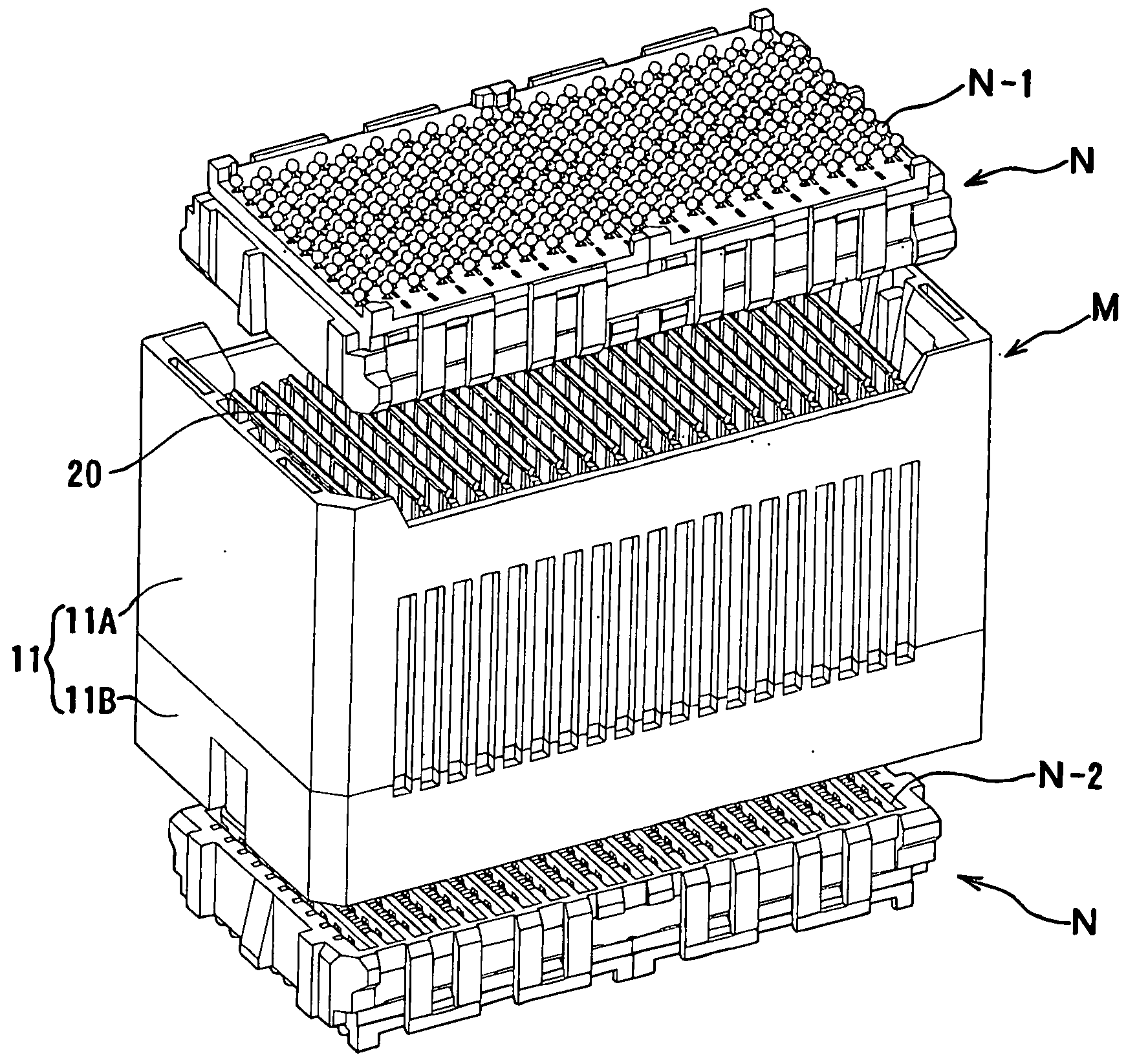
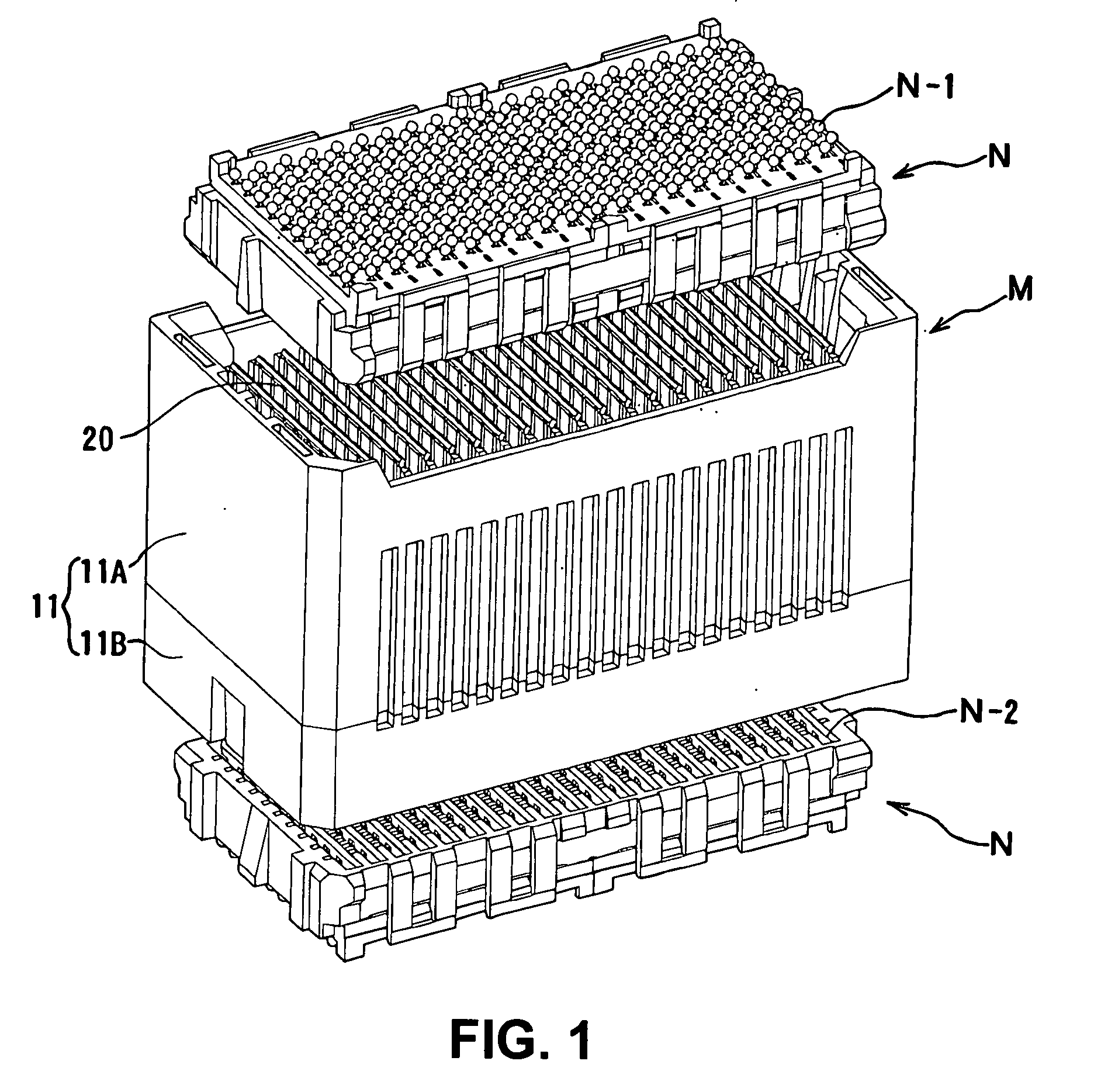
[0040]FIG. 1 is a perspective view showing a middle electrical connector M (middle connector) and board electrical connectors N (board connector N) according to an embodiment of the present invention in a state before fitting. The board connectors N are connected to the middle connector M.

[0041]In the embodiment shown in FIG. 1, the board connectors N with an identical configuration are situated above and below the middle connector M symmetrically. In FIG. 1, solder balls N-1 are provided on a top surface of the board connector N situated above the middle connector and a bottom surface of the board connector N situated below the middle connector M to connect with a circuit board (not shown). The board connector N (bottom board connector N) has a plurality of receiving grooves N-2 on an opposite side of the side provided with the solder balls N-1. Middle members 20 of t...


PUM


Abstract

A middle electrical connector includes a plurality of terminals disposed on a terminal arrangement plate. A housing holds the terminal arrangement plate. The terminal arrangement plate has retaining grooves to hold the terminals at a plurality of positions. The retaining grooves includes a front retaining groove and a back retaining groove having at least one of a shape or a size different with each other. The front retaining groove holds a front retained portion of the terminal on a front portion side. The rear retaining groove holds a rear retained portion of the terminal on a rear portion side. When the terminal is inserted, the front retained portion is allowed to pass through the rear retaining groove.

Description

BACKGROUND OF THE INVENTION AND RELATED ART STATEMENT[0001]The present invention relates to a middle electrical connector intervening between two connectors to connect the two connectors.[0002]A conventional middle electrical connector has a middle member. Two mating connectors are fitted into the middle member to electrically connect with each other through the middle member. The middle member includes an arrangement plate made formed of an insulation member, and is provided with a terminal on a surface of the arrangement plate. The terminal extends between two edge portions of the arrangement plate situated on opposite sides thereof, so that the two mating connectors are fitted into the middle electrical connector in the edge portions. The terminal and the arrangement plate may be molded together to hold the terminal on the arrangement plate. However, a cost of such a molding method is generally high.[0003]Instead of molding the terminal and the arrangement plate together, an arra...

Claims


Application Information

Patent Timeline
Patent Type & Authority Applications(United States)
IPC IPC(8): H01R9/22
CPCH01R23/688H01R13/41H01R13/6585H01R12/7082
Inventor NAGATA, MASAKAZU
Owner HIROSE ELECTRIC GROUP
Why Eureka
Try Eureka