
Flexion control ankle joint with spherical hinge

a technology of spherical hinges and ankle joints, applied in the field of orthoses, can solve the problems of cracks and possible failures, difficult installation of other prior art ankle joints, and extra time, and achieve the effects of generating minimal interference with the patient's shoes, facilitating setting, and simplifying and speeding up the fabrication and fitting process

Active Publication Date: 2009-03-12
JACKOVITCH TIMOTHY
View PDF34 Cites 8 Cited by
  • Summary
  • Abstract
  • Description
  • Claims
  • Application Information

AI Technical Summary

Benefits of technology

[0015]One advantage of the invention is that the joint hinge tolerates misalignment and nonparallel mounting surfaces with respect to the leg brace, simplifying and speeding the fabrication and fitting process.
[0016]A further advantage of the invention is that the ankle joint assembly is compact in length and width and thin in the rotation axis dimension, generating minimal interference with the patient's shoes and allowing use with smaller patients, such as pediatric patients.
[0017]Another advantage of the invention is that the range of motion of the joint hinge and therefore a leg brace can be easily set by the patient or practitioner.
[0018]Another advantage of the invention is that a range limiting system allows the patient or practitioner to set a continuum of settings to meet the individual needs of a patient.
[0019]Another advantage of the invention is that the threaded rods in the range limiting system are set in the anterior and posterior directions.

Problems solved by technology

However, these and other prior art ankle joints are often difficult to install, requiring precisely parallel mounting surfaces for medial and lateral joint mechanisms.
Without proper mounting the joints may be subject to greater wear, binding, and stress on the leg brace components, leading to cracks and possible failure.
Achieving proper installation requires additional shimming or shaping or remaking of the leg brace components, taking extra time for the practitioner and potentially leading to extra complication and cost for the patient.
Devices that offer plantar flexion control include devices that are bulky and difficult to fit in the patient's shoe, and are difficult to adjust due to the fact that they include definite settings that can only be adjusted in increments.
Often these devices are large and cause additional complications with smaller patients, such as pediatric patients.

Method used


Image

  • Flexion control ankle joint with spherical hinge
  • Flexion control ankle joint with spherical hinge
  • Flexion control ankle joint with spherical hinge

Examples


Embodiment Construction

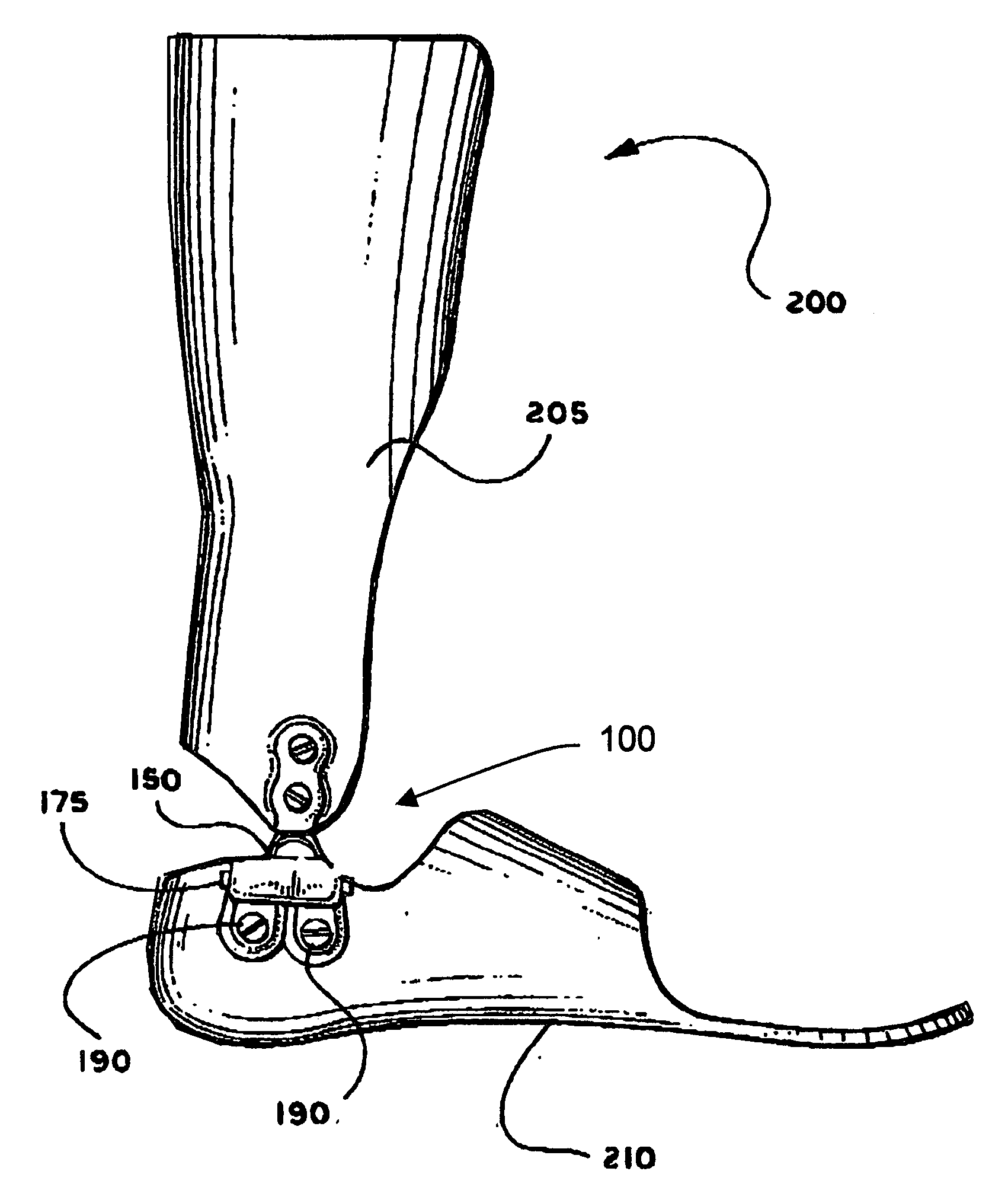
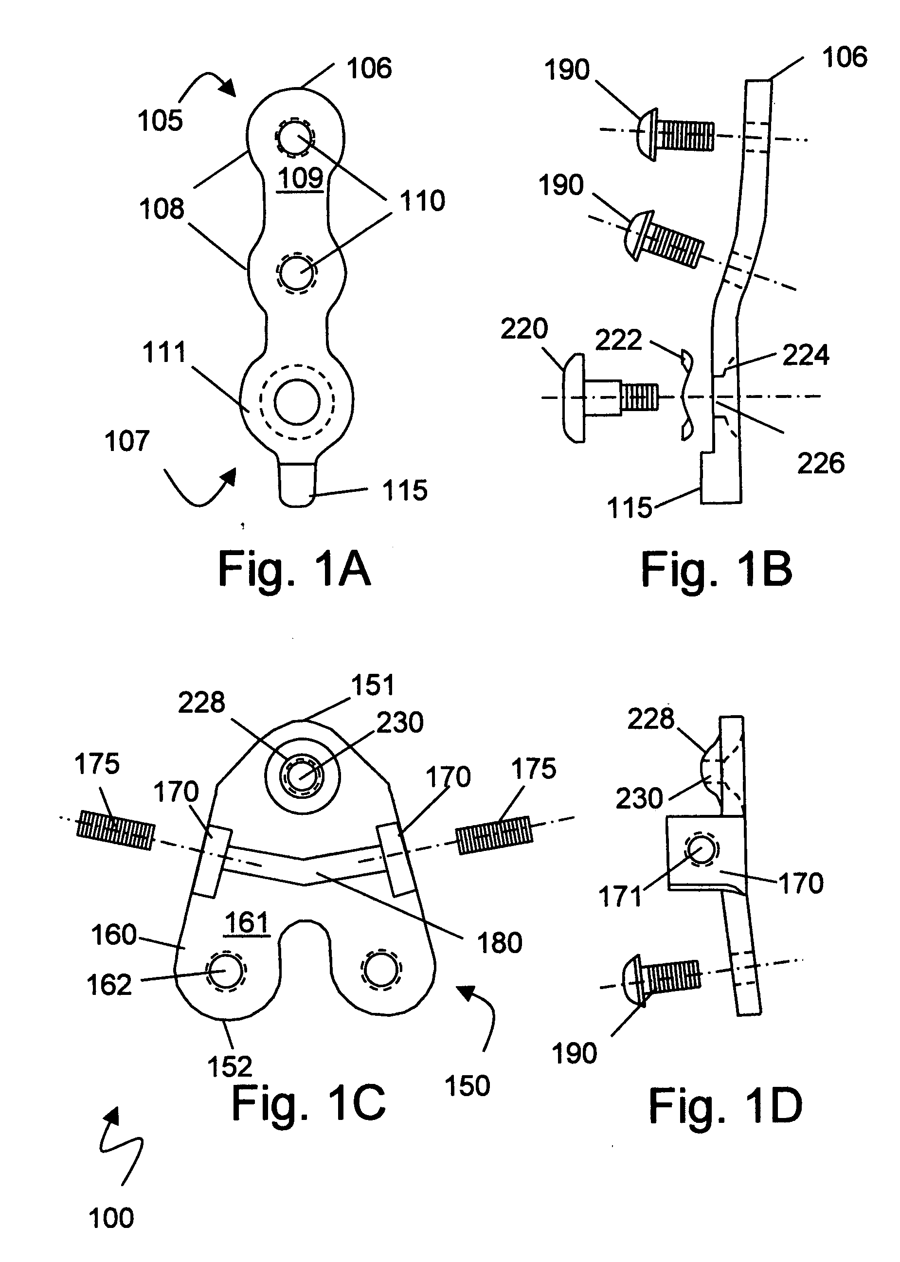
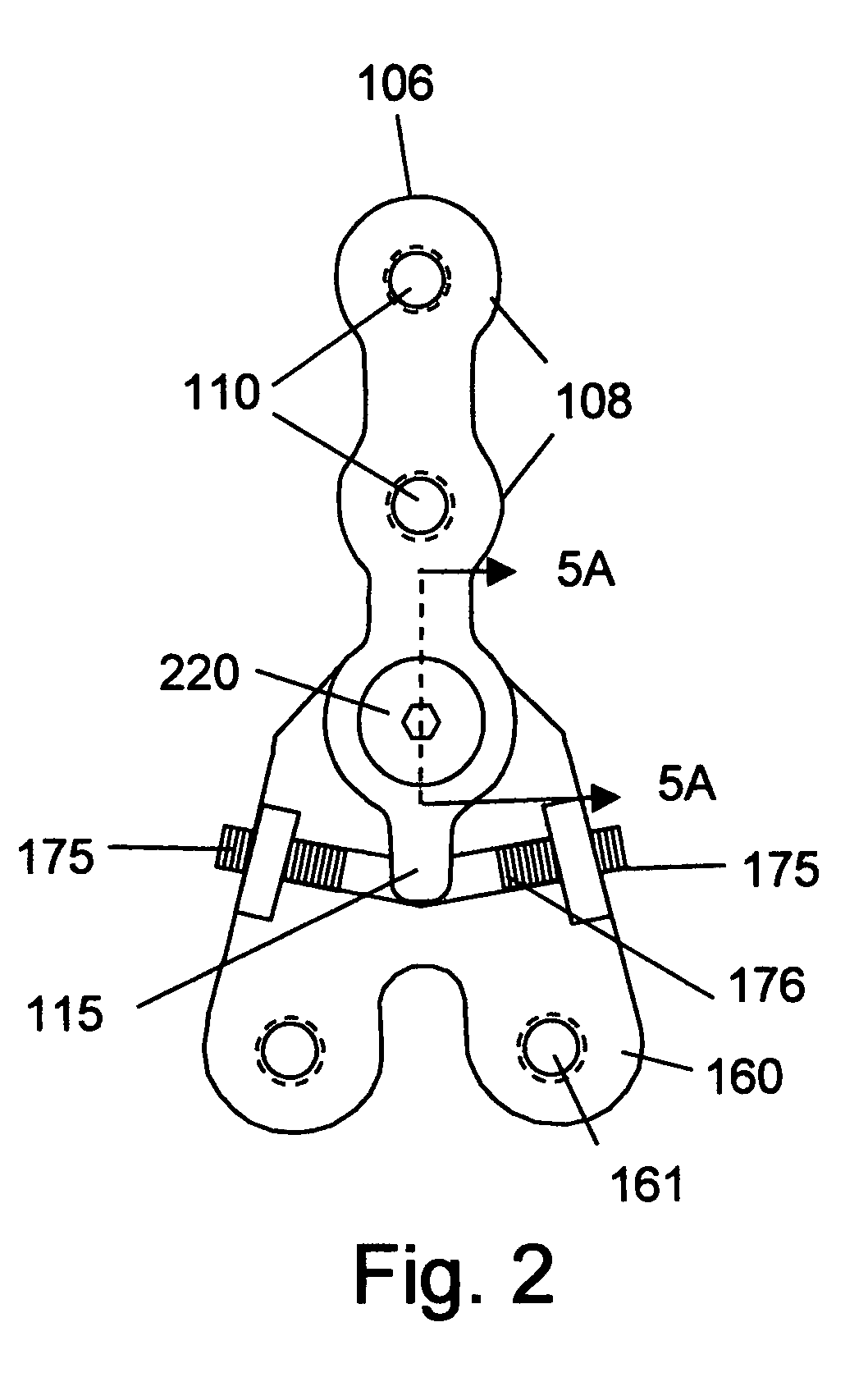
[0033]The present invention pertains to an ankle joint providing rigid vertical support, allowing free ankle rotation within adjustable plantar and dorsiflexion limits while allowing angular misalignments that simplify fabrication and adjustment of a leg brace utilizing the ankle joint. The ankle joint results in a compact assembly easily adapted to smaller patients, including pediatric patients. These capabilities are achieved by an ankle joint comprising a proximal and distal plate joined by a spring loaded spherical dome hinge. The spherical dome is formed in one component, typically the distal plate, and a mating recess is formed in the other component, typically the proximal plate. The assembly is held together by a captive screw and spring wave washer. The distal plate further includes a rotation range limiting mechanism including dorsiflexion and plantar flexion limit adjustments. These features may be better understood with reference to the figures.

[0034]FIG. 1A-FIG. 1D illu...


PUM


Abstract

A joint hinge and a leg brace having the joint hinge that includes a spring loaded spherical joint for coupling a proximal portion and a distal portion of the joint hinge. The spherical joint includes a dome on one portion coupled to a mating cup on the other portion. A wide-headed pin, typically a shoulder screw, captivates the cup against the sphere. A spring washer may be included to provide a preloading force to mate the cup to the dome. The spherical portion may be pressed or stamped into one portion of the hinge or fabricated separately and attached. In one embodiment, the dome is fabricated of sintered bearing material and may be impregnated with lubricant. The spherical joint functions in conjunction with an adjustable flexion range limiting system that include rods that are threaded and easy to screw in and out as the patient's range of motion changes.

Description

BACKGROUND[0001]1. Field of the Invention[0002]The present invention relates generally to the field of orthotic devices and more particularly to ankle foot orthoses with a flexion control ankle hinge apparatus, system and method.[0003]2. Background of the Invention[0004]Present ankle joints for leg braces can offer control of plantar flexion and dorsiflection as shown in U.S. Pat. No. 6,929,614 issued Aug. 16, 2005 to Jackovitch, which is incorporated herein by reference. However, these and other prior art ankle joints are often difficult to install, requiring precisely parallel mounting surfaces for medial and lateral joint mechanisms. Without proper mounting the joints may be subject to greater wear, binding, and stress on the leg brace components, leading to cracks and possible failure. Achieving proper installation requires additional shimming or shaping or remaking of the leg brace components, taking extra time for the practitioner and potentially leading to extra complication ...

Claims


Application Information

Patent Timeline
IPC IPC(8): A61F5/00
CPCY10T16/524A61F5/0127
Inventor JACKOVITCH, TIMOTHY
Owner JACKOVITCH TIMOTHY
Learn More