

Eye surgical tool
a surgical tool and eye technology, applied in the field of surgical instruments, can solve the problems of requiring the tool size to increase beyond the usable biometric design of handheld instruments, and the maximum strain limit of the piezoelectric materials themselves, so as to improve the accuracy of actuation, improve the amplification effect, and reduce the effect of strain
- Summary
- Abstract
- Description
- Claims
- Application Information
AI Technical Summary
Benefits of technology
Problems solved by technology
Method used
Image


Examples
first embodiment
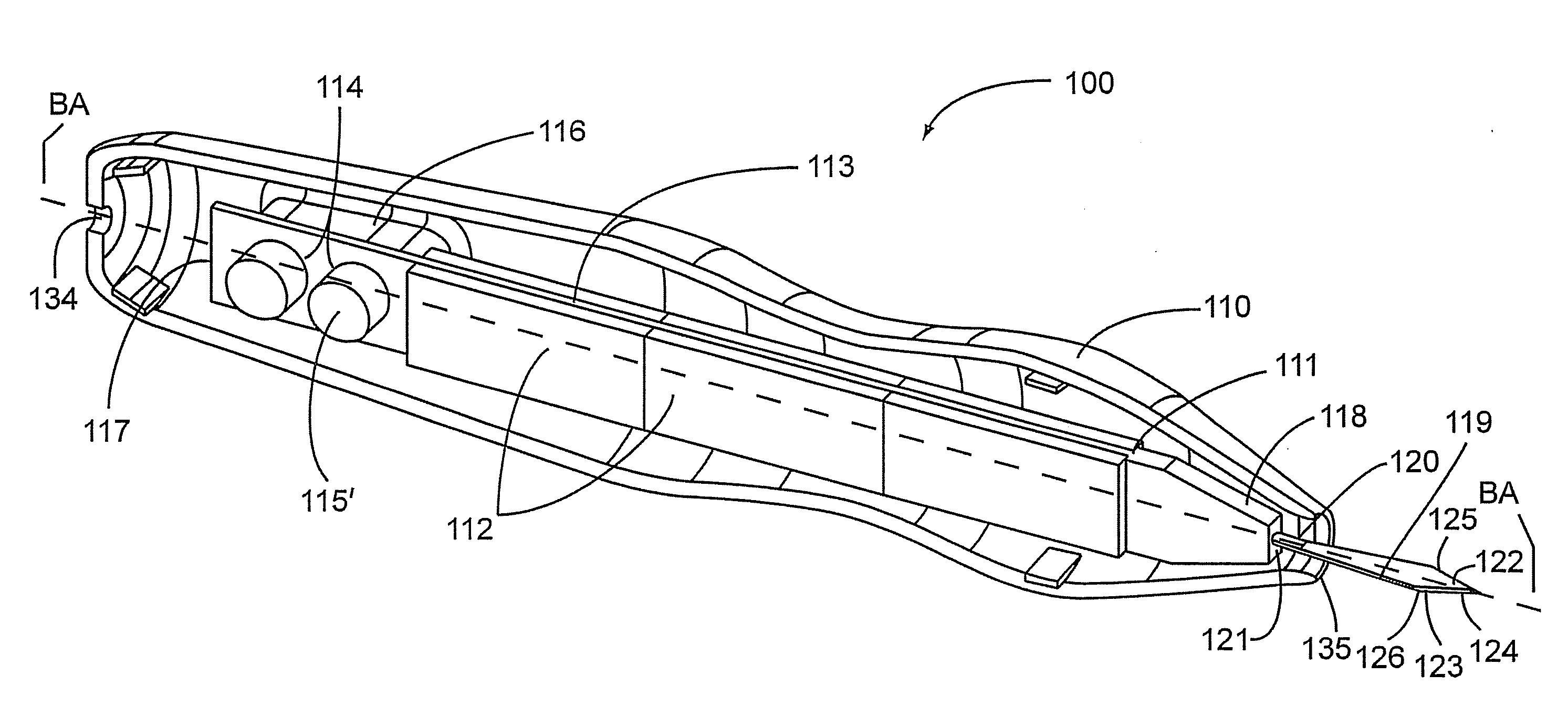
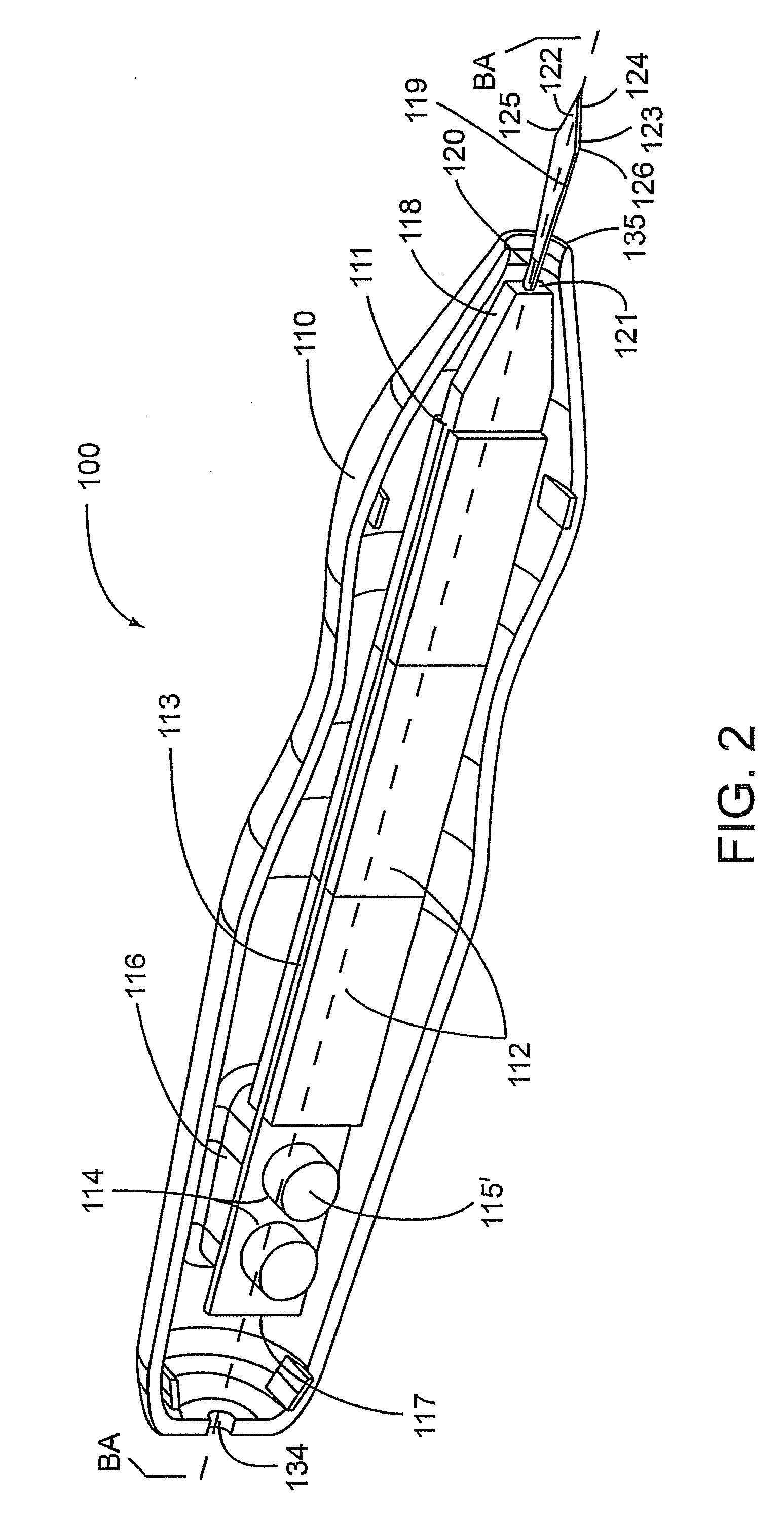
[0137]In the present invention as shown in FIG. 2, a bender actuated surgical tool 100 comprises a body 110, and a bimorph piezoelectric transducer / transducer / actuator 111 disposed within body 110. The bimorph piezoelectric transducer / transducer / actuator 111 comprises at least one piezoelectric ceramic plate 112, but preferably comprises more than one of piezoelectric ceramic plates 112 attached longitudinally upon at least one side of a bender support bar 113. The bender support bar 113 comprises a distal end 117 and a proximal end 118, with a bender motion constraint 114 at the distal end 117. The bender motion constraint 114 attaches bender support bar 113 to surface 116 of the body 110. In one embodiment, the bender motion constraint 114 of the present embodiment comprises at least one thru-hole 115 (not visible in this figure) and a bolt 115′ passing at least partly through the bender support bar 113 and into an attachment slot (not shown) formed on support surface 116. The att...
second embodiment
[0148]In a second embodiment, the surgical tool of the present invention can be a cymbal actuated surgical tool 200 as shown in FIG. 6. Surgical tool 200 comprises a body 210 and a cymbal actuator 211 which further comprises a piezoelectric ceramic disc 212 stacked between a first end-cap 213 and a second end-cap 214. The first end-cap 213 is fixedly attached to the body 210. Additionally, surgical tool 200 comprises a blade such as a dual beveled angled slit split blade 215. A blade neck 216 is coupled at one end to the second end-cap 214 at attachment node 217, and the blade at an opposite end. A motion constraining yoke 218 is attached to the blade neck at a location between the blade and the attachment node. In one configuration, the motion constraining yoke 218 has a cylindrical shape having an outer diameter with a hollow center defining an inner diameter. The blade neck may be connected to the motion constraining yoke at the inner diameter while the outer diameter is attached...
third embodiment
[0151]Turning the attention over to FIG. 7, the invention is shown as a Langevin actuated surgical tool 300. Langevin style transducers have a stack of piezoelectric ceramic discs 313 as shown in FIG. 7. In this embodiment, the surgical tool 300 comprises a body 310 and a conventional Langevin actuator 311 disposed within the body and fixedly held in place at body support collar 312. The Langevin actuator comprises at least one, but preferably more than one piezoelectric ceramic disc 313, a backing portion 314, a horn portion 315 and a compression bolt 316. Horn portion 315 terminates at a proximal end of body 310, and comprises an attachment node 317, which allows a motion transfer adaptor 318 to be mechanically connected to the Langevin actuator. The motion transfer adaptor 318 at one end is functionally attached to attachment node 317 while a blade 319 is attached at another end. A hypothetical long axis HLA runs continuously through the center of each of a distal portion of body...
PUM
 Abstract
Description
Claims
Application Information