Vehicle HVAC and Battery Thermal Management

a technology for battery thermal management and vehicles, applied in the direction of battery/fuel cell control arrangement, vessel parts, vessel construction, etc., can solve the problems of reducing the battery power only range of these vehicles, and increasing the cost and weight. , to achieve the effect of reducing the negative pressure in the cabin, reducing the cost and weight, and increasing the battery performance and battery li

Inactive Publication Date: 2009-03-19
GM GLOBAL TECH OPERATIONS LLC
View PDF7 Cites 144 Cited by
  • Summary
  • Abstract
  • Description
  • Claims
  • Application Information

AI Technical Summary

Benefits of technology

[0008]An advantage of an embodiment is that the vehicle HVAC module is employed not only to heat and cool the passenger cabin, but also the battery pack. Thus, no additional supplemental HVAC system is required for heating and cooling the battery pack. One may employ supplemental heating in the battery pack if desired, or just use heating from HVAC system. Also, no additional filtration or water separation is required for battery pack heating and cooling since the HVAC module takes care of these functions for both.
[0009]An advantage of an embodiment is that, even though no separate battery HVAC system is employed, simultaneous cabin heating and battery cooling can be achieved and vice versa.
[0010]An advantage of an embodiment is that the passenger cabin and the battery can be preconditioned (i.e., a more desirable temperature achieved) prior to occupants entering the vehicle. This preconditioning may be activated by a key f

Problems solved by technology

In addition, with these vehicles, it is sometimes desirable to heat the passenger cabin while cooling the battery, and vice versa.
It is desirable to reduce or eliminate such supplemental HVAC systems that are used to heat and cool the battery pa

Method used


Image

  • Vehicle HVAC and Battery Thermal Management
  • Vehicle HVAC and Battery Thermal Management
  • Vehicle HVAC and Battery Thermal Management

Examples


second embodiment

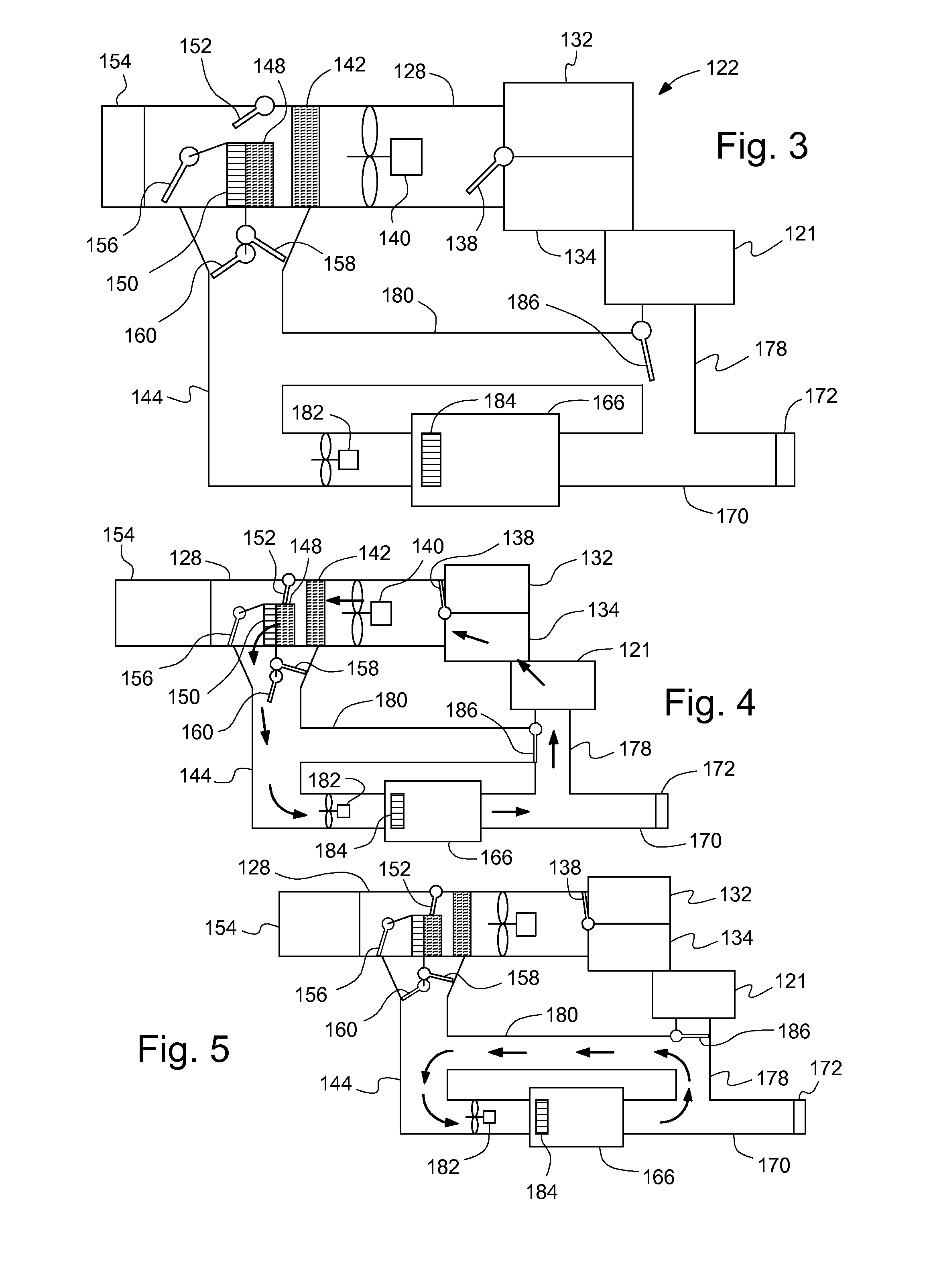
[0028]The second embodiment adds some features to enhance the flexibility of the HVAC and battery thermal management system 122. A battery-to-cabin recirculation duct 178 is added that connects the pressure relief duct 170 and the cabin 121. Also, a battery recirculation duct 180 connects the battery-to-cabin recirculation duct 178 to the battery duct 144. A battery recirculation valve 186 is located at the intersection of the battery-to-cabin recirculation duct 178 and the battery recirculation duct 180. This valve 186 selectively directs air flow into the battery recirculation duct 180 or into the cabin 121. An optional battery blower 182 is located in the battery duct 144 upstream of the battery pack 166 to supplement the HVAC blower 140 or provide flow when battery air recirculation (discussed below) is desired. Also, an optional battery heater 184 is located in the battery pack 166 to supplement heat from the heaters 148, 150 or provide heat when battery air recirculation and b...

fourth embodiment

[0036]FIG. 9 illustrates a Since this embodiment is similar to the second, similar element numbers will be used for similar elements, but employing 300-series numbers. In this embodiment cooled air flow is shown flowing through both the passenger cabin 321 and the battery pack 366 simultaneously. These air flow paths allow for cooling the battery pack 366 and cabin 321 while operating the vehicle.

[0037]For the first air flow path, the HVAC blower 340 draws part of its air through the recirculated air inlet 334 and the rest through the outside air inlet 332, and directs it through the evaporator 342, where it is cooled. With the temperature control and shutoff valve 356 and the battery heating valve 360 closed, and the battery cooling valve 358 open, a portion of the air flows through the battery duct 344, through the battery pack 366 and into the pressure relief duct 370. The air flow then flows partially out through the body pressure relief vent 372, and partially through the batt...

fifth embodiment

[0038]FIG. 10 illustrates a Since this embodiment is similar to the first, similar element numbers will be used for similar elements, but employing 400-series numbers. This vehicle 420 has a passenger cabin 421 that has an automated way to allow air to escape from a mid to upper portion of the cabin 421. The air escape may be an automatically opening sun roof 497 or may be reverse air flow 433 through a portion of a vehicle cowl in communication with the HVAC module 428 of the HVAC portion 424. For this vehicle, a battery pack 466 still connects to the HVAC module 428 via the battery duct 444 and connects to the body pressure relief vent 472 via the pressure relief duct 470. The body pressure relief vent 472 for this embodiment, however, is controllable. That is, it is electronically controllable to allow for reverse flow through the vent in certain situations. Optionally, the body pressure relief vent 472 may include a screen or baffle (not shown) to minimize the possibility for d...


PUM


Abstract

A HVAC and battery thermal management system for a vehicle having a HVAC portion and a battery portion, and a method of operation, is disclosed. The HVAC portion may include a main chamber, an evaporator located in the main chamber, a heater extending across a portion of the main chamber downstream of the evaporator, a battery duct extending from the main chamber adjacent to the heater and in fluid communication with the main chamber both upstream and downstream of the heater. The battery portion may include a battery pack in fluid communication with the battery duct, a battery cooling valve located in the battery duct and configured to selectively allow fluid flow from the main chamber between the evaporator and the heater, and a battery heating valve located in the battery duct and configured to selectively allow fluid flow from the main chamber downstream of the heater.

Description

BACKGROUND OF INVENTION[0001]The present invention relates generally to a vehicle having a heating ventilation and air conditioning (HVAC) system and an air cooled / heated battery pack.[0002]Some modern automotive vehicles are propelled by electric motors, whether a hybrid electric vehicle, a pure electric vehicle, or some other similar type of vehicle. These vehicles include battery packs for storing electric charge used to drive the motor. A significant amount of energy flow into and out of the battery pack can occur, which may raise the temperature of the battery pack above levels that are desirable. Also, the batteries operate better when above a certain low temperature range. Consequently, some of these vehicles use various techniques for cooling and heating the battery pack. Given the additional cost and complexity of cooling a battery pack, it is thus desirable to cool and heat it in the most efficient and least costly way possible.[0003]In addition, with these vehicles, it is...

Claims


Application Information

Patent Timeline
IPC IPC(8): B60H1/02
CPCB60H1/00278B60L2240/662B60R16/04H01M10/5004H01M10/5006H01M10/5016H01M10/5067H01M10/5073H01M10/5079H01M10/5095Y02T10/7077Y02T10/705Y02T90/16Y02T90/34Y02T10/7291Y02T10/70B60L1/003B60L1/02B60L3/0046B60L11/14B60L11/1805B60L11/1874B60L11/1875B60L11/1877B60L11/1879B60L11/1887B60L2240/34B60L2240/545B60H2001/003H01M10/625H01M10/615H01M10/663H01M10/6563H01M10/6569H01M10/6566H01M10/613B60L50/16B60L50/52B60L58/26B60L58/27B60L50/66B60L50/64B60L58/40Y02T10/72Y02T10/7072Y02E60/10Y02T90/40
Inventor MAJOR, GREGORY A.PLEUNE, JEFFREY M.
Owner GM GLOBAL TECH OPERATIONS LLC
Why Eureka
Try Eureka