Membrane cover having a protective layer to prevent deterioration of UV stabilizers therein

a membrane cover and protective layer technology, applied in the field of membrane covers, can solve the problems of deterioration of uv stabilizers in the membrane cover, loss of uv protection, and inability to address the problem of uv stabilizer deterioration in the membrane cover

Inactive Publication Date: 2009-03-19
GEOMEMBRANE TECH
View PDF3 Cites 8 Cited by
  • Summary
  • Abstract
  • Description
  • Claims
  • Application Information

AI Technical Summary

Benefits of technology

The patent describes a way to make a membrane cover that is resistant to wind-induced fluttering. This is achieved by using two layers of foam that are about half an inch thick. This stiffness prevents the membrane cover from fluttering in response to wind.

Problems solved by technology

The technical problem addressed in this patent text is the deterioration of UV stabilizers in membrane covers used in wastewater reservoirs in warm-weather regions where the covers are exposed to sunlight. This deterioration is caused by the porosity of the membrane cover increasing with temperature and the bio-gases generated under the cover reacting with the metal oxides in the UV stabilizers. The text suggests that an improved membrane structure is needed to better prevent the degradation of the UV stabilizers.

Method used


Image

  • Membrane cover having a protective layer to prevent deterioration of UV stabilizers therein
  • Membrane cover having a protective layer to prevent deterioration of UV stabilizers therein
  • Membrane cover having a protective layer to prevent deterioration of UV stabilizers therein

Examples


Embodiment Construction

[0019]While this invention is susceptible of embodiment in many different forms, there is shown in the drawings and will be described in details herein one specific embodiment, with the understanding that the present disclosure is to be considered as an example of the principles of the invention and is not intended to limit the invention to the embodiment illustrated and described.

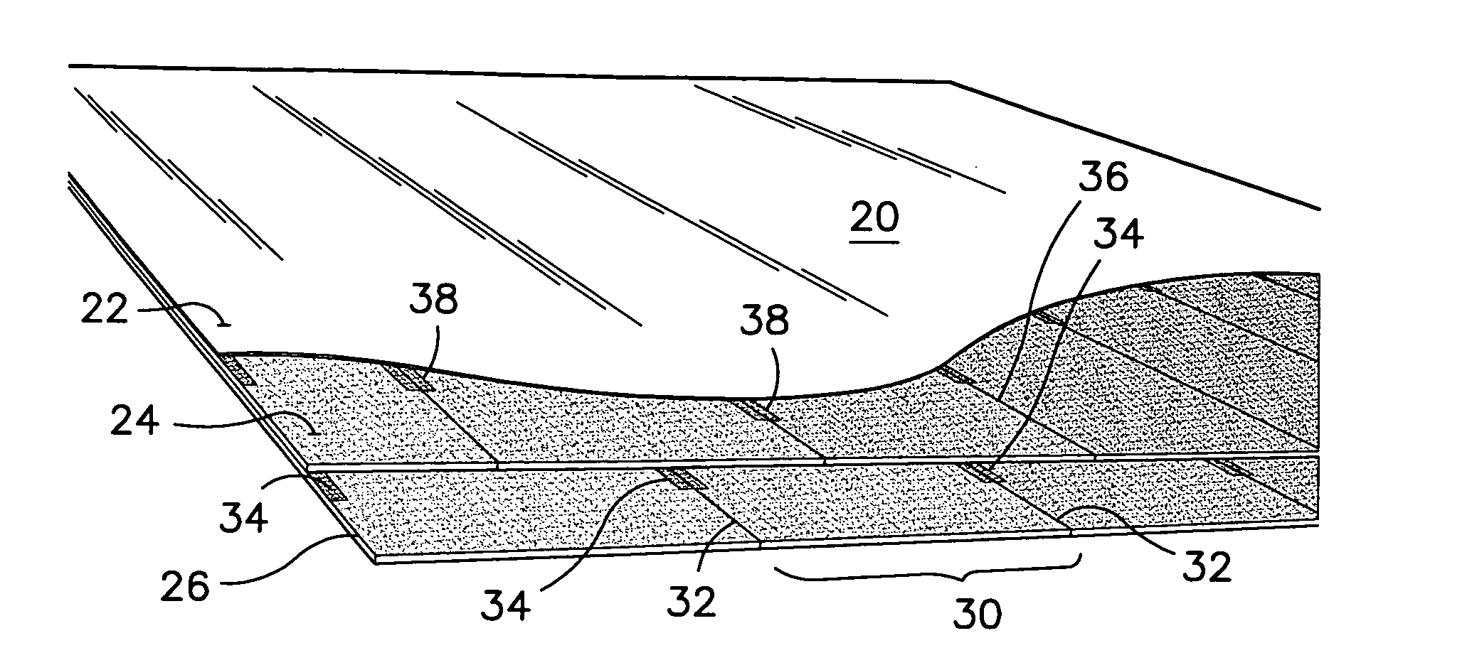
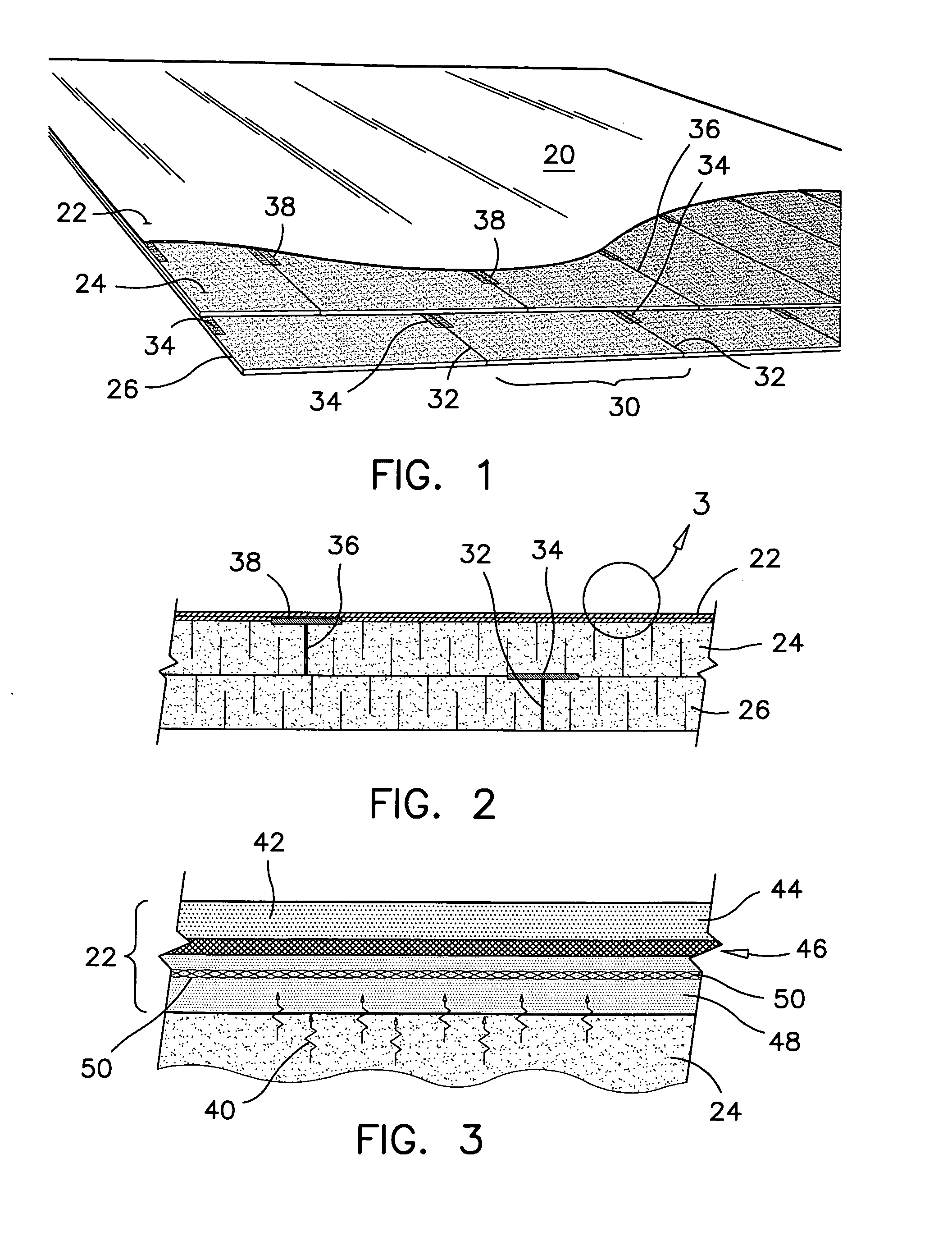
[0020]The preferred membrane structure 20 is partially illustrated in FIG. 1. The preferred membrane structure 20 is made of a top layer 22 bonded to two foam layers 24, 26. The foam layers 24, 26 are made of semi-rigid foam insulation. The top layer 22 is impermeable to water and gas and is resistant to ultraviolet radiations. The two foam layers 24, 26 are bonded together and to the top layer 22, as illustrated in FIGS. 1 and 2. The bonding of the three layers is effected by hot-melt welds.

[0021]One of the foam layers constitutes a bottom layer 26 and is intended to be in contact with the liquid surface ...


PUM


Abstract

The membrane structure according to the present invention has a top layer containing three plies. The top ply has UV stabilizers embedded therein; the bottom ply has stretch-resistant elements embedded therein; and the middle ply contains a co-extruded polyvinylidene chloride barrier film for example, for protecting the top ply against bio-gas infiltrations therein. In another aspect, the top and bottom plies containing polyethylene for protecting the middle ply from the weather and from corrosive environments under the membrane cover. In yet another aspect, the membrane structure has two foam layers affixed to the bottom ply. Each foam layer is made of juxtaposed strips of semi-rigid, closed-cell, polyethylene foam; wherein each strip in one foam layer is laid astride the adjoining edges of a pair of strips in the other foam layer. The strips of foam are bonded together and to the undersurface of the bottom ply by strips of fused polyethylene.

Description


Claims


Application Information

Patent Timeline
Owner GEOMEMBRANE TECH
Why Eureka
Try Eureka