Stapler

a stapler and flat-type technology, applied in the field of flat-type staplers, can solve the problems of enlarged base portion and raised back end of staplers

Inactive Publication Date: 2009-03-19
PLUS STATIONARY CORP
View PDF22 Cites 19 Cited by
  • Summary
  • Abstract
  • Description
  • Claims
  • Application Information

AI Technical Summary

Benefits of technology

[0015]According to the stapler of the invention, since the roller is disposed between the handle member and the push-down portion so as to fasten together sheets of paper by making use of the principle of leverage, a thick bundle of papers can be fastened together with a small magnitude of force. In addition, since the push-down portion is rotatably attached to the position on the base portion which lies in the vicinity of the rear end thereof and the handle member is rotatably attached to the position on the handle support member which lies in the vicinity of the front end thereof, the center of gravity of force applied at the time of clinching is situated in the vicinity of the center of the base portion, and since the front of the base portion does not have to be formed large, the stapler can be provided which is small in size and which can fasten together a large number of sheets of paper.
[0016]In addition, since the magazine portion is made to be of the front loading type, the handle member or the like does not have to be rotated largely when accommodating staples therein, whereby the accommodation of staples can be implemented through simple accommodating work.

Problems solved by technology

In the desktop stapler that has been described above, although a large magnitude of force becomes necessary to fasten together a large number of sheets of paper, since the handle is pivotally attached to rotate to a position on the base portion which lies in the vicinity of a rear end thereof, when such a large magnitude of force is applied to the vicinity of a distal end of the handle, there has been caused a problem that the rear end of the stapler is raised.
In addition, in order to solve this problem, there is a method in which the base portion is formed long at the front thereof, but this has triggered another problem that the base portion is enlarged.

Method used


Image

  • Stapler
  • Stapler
  • Stapler

Examples


Embodiment Construction

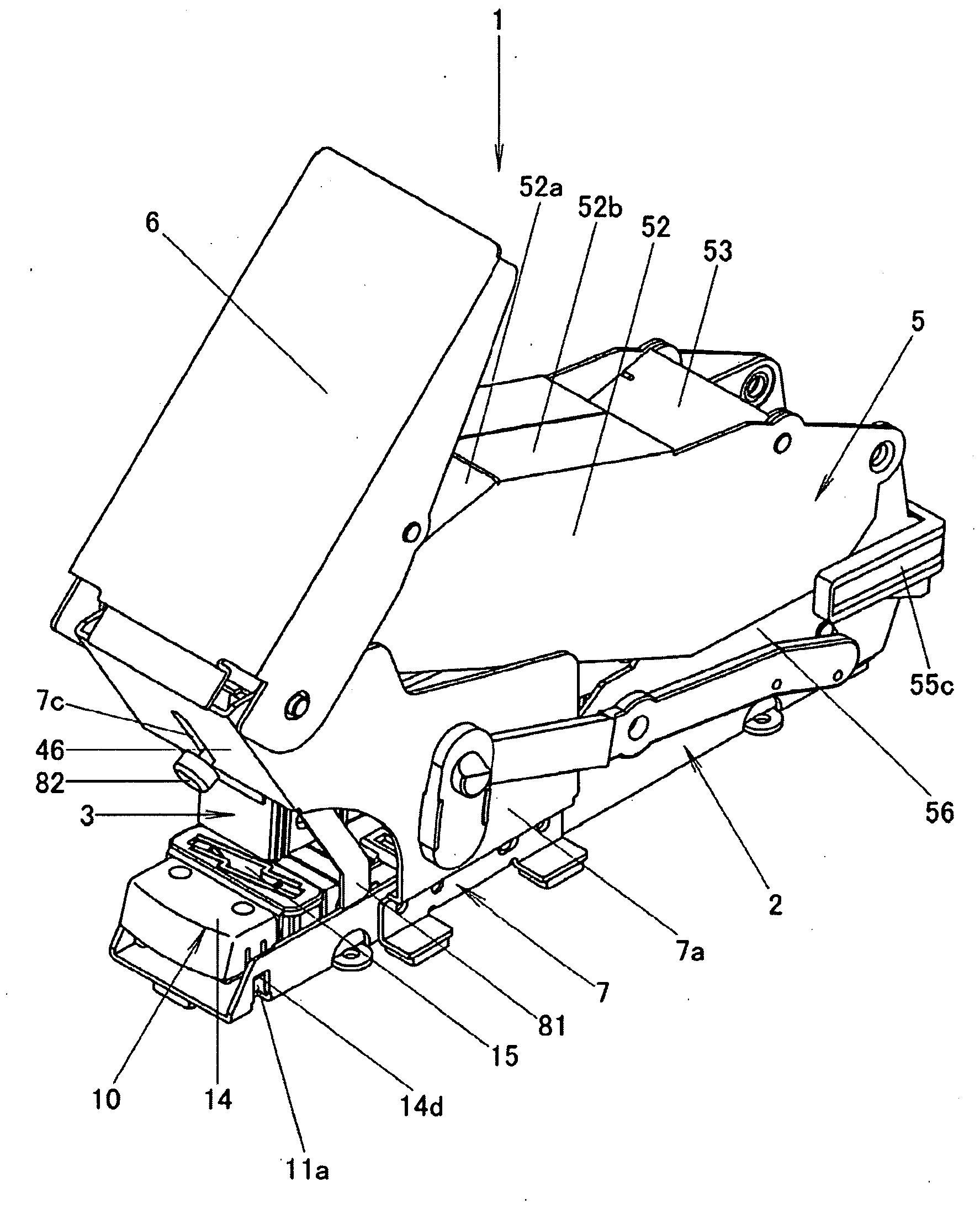
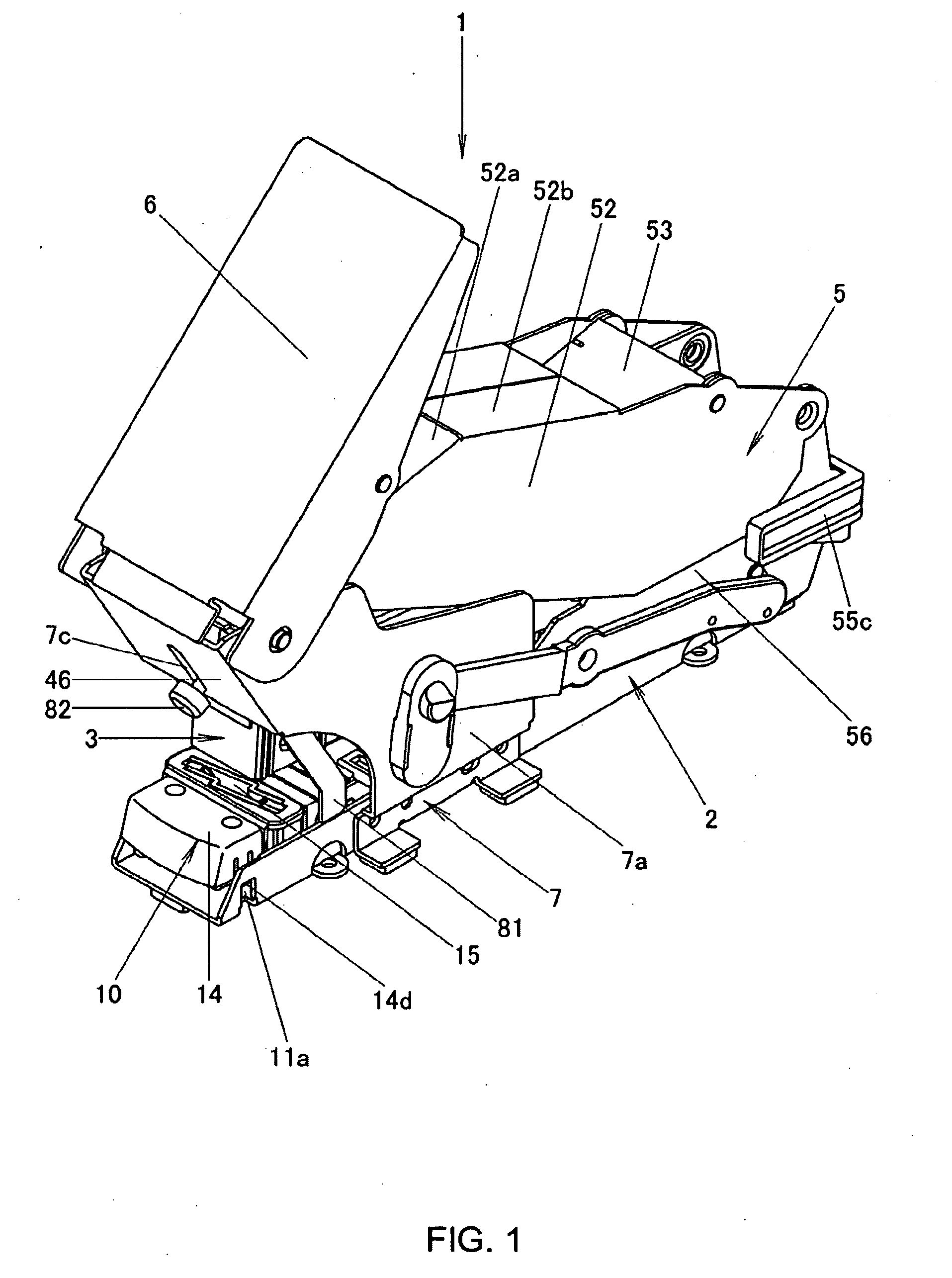
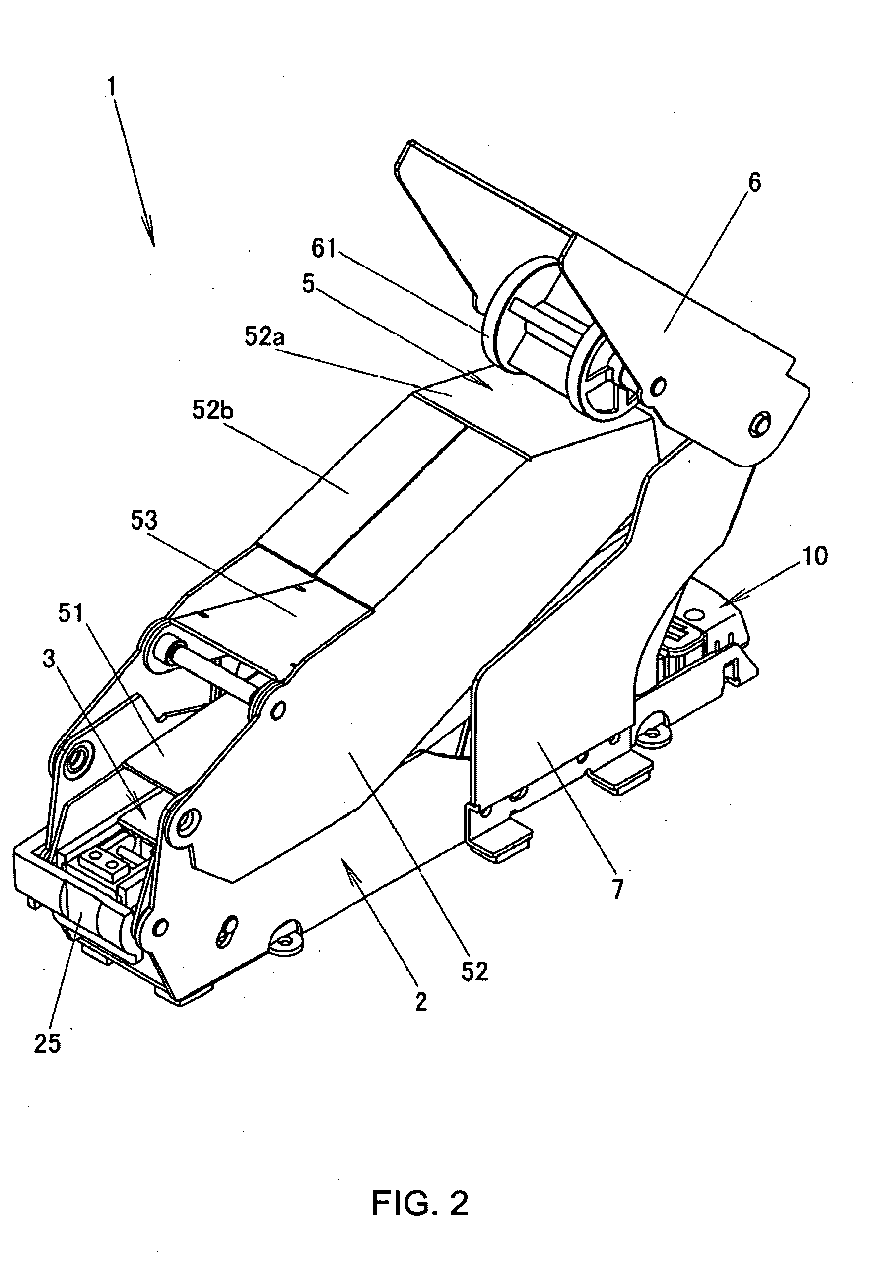
[0035]A stapler 1 according to a best mode for carrying out the invention is such as to have a base portion 2 which includes a rotatable clinching portion 10, a magazine portion 3 which is pivotally attached to rotate to a position on the base portion 2 which lies in the vicinity of a rear end thereof by a spindle 25 and is disposed above the base portion 2, a push-down portion 5 which is pivotally attached to rotate to a position on the base portion 2 which lies in the vicinity of the rear end thereof, which has a driving blade 46 in the vicinity of a front end thereof and which is disposed above a magazine portion 3, and a handle member 6 which is pivotally attached to rotate to a handle support member 7 which is fixed to the base portion 2 at a portion which lies in the vicinity of a front end thereof and which is adapted to lower the push-down portion 5 by being brought into contact with the vicinity of a front end of an upper portion of the push-down portion 5.

[0036]In addition...


PUM


Abstract

In order to provide a stapler in which a large volume of paper can be fastened together with a small magnitude of force in a stable fashion, there is provided a stapler 1 having a base portion 2 which comprises a rotatable clinching portion 10, a magazine portion 3 which is pivotally attached to rotate to a position on the base portion 2 thereabove which lies in the vicinity of a rear end thereof by a spindle 25, a push-down portion 5 which is pivotally attached to rotate to a position on the base portion 2 which lies in the vicinity of the rear end thereof in such a manner as to be disposed above the magazine portion 3 and which has a driving blade 46 in the vicinity of a front end thereof, and a handle member 6 which is pivotally attached to rotate to a handle support member 7 which is fixed to the base portion 2 in a position on the handle member 6 which lies in the vicinity of a front end thereof and which is adapted to be brought into contact with the vicinity of a front end of an upper portion of the push-down member 5 so as to lower the push-down member 5, wherein the clinching portion 10 comprises a slider 13 which slides along sliding support shafts 17 to permit a lowering operation of the clinching portion 10, and wherein the handle member 6 comprises a roller 61 in a position which is in contact with the push-down portion 5.

Description

BACKGROUND OF THE INVENTION[0001]1. Technical Field[0002]The present invention relates to a flat type stapler in which pointed end portions of a staple are bent flat after it has penetrated, for example, sheets of paper to be fastened together.[0003]2. Background Art[0004]A stapler is stationery for fastening together sheets of paper and is one of inevitable office materials. There have been proposed many staplers. In staplers, there are two types of staplers: one is a type in which pointed end portions of a stapler are bent in a curved fashion after it has penetrated sheets of paper to be fastened together, and the other type is a flat type in which pointed end portions of a stapler are bent flat after it has penetrated sheets of paper to be fastened together.[0005]A general flat type stapler includes a base portion having a clincher, a magazine for accommodating strips of staples, a handle that is pivotally attached to rotate to a position on the base portion which lies in the vic...

Claims


Application Information

Patent Timeline
Patent Type & Authority Applications(United States)
IPC IPC(8): B25C5/11
CPCB25C5/11B25C5/0242B25C5/02
Inventor MATSUKAWA, TAKESHI
Owner PLUS STATIONARY CORP
Why Eureka
Try Eureka