Coaxial Tube Damper

a damper and coaxial tube technology, applied in the direction of mechanical equipment, machine supports, manufacturing tools, etc., can solve problems such as pain or injury to users, and achieve the effect of reducing the amount of vibrations fel

Active Publication Date: 2009-03-19
MCP IP
View PDF68 Cites 10 Cited by
  • Summary
  • Abstract
  • Description
  • Claims
  • Application Information

AI Technical Summary

Benefits of technology

[0007]In at least one embodiment, at least one portion of a device that transmits vibrations during use has a dampening portion that reduces the amount of vibrations felt ...

Problems solved by technology

These vibrations can cause fatigue and discomfort during use and, in so...

Method used


Image

  • Coaxial Tube Damper
  • Coaxial Tube Damper
  • Coaxial Tube Damper

Examples


Embodiment Construction

[0024]While this invention may be embodied in many different forms, there are described in detail herein specific embodiments of the invention. This description is an exemplification of the principles of the invention and is not intended to limit the invention to the particular embodiments illustrated.

[0025]For the purposes of this disclosure, like reference numerals in the figures shall refer to like features unless otherwise indicated.

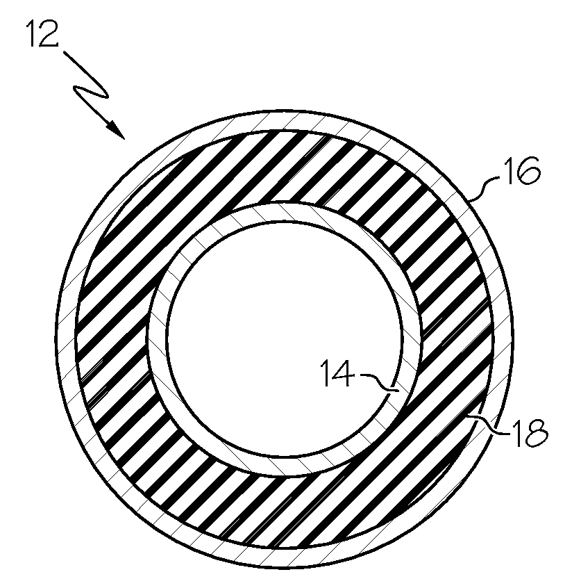
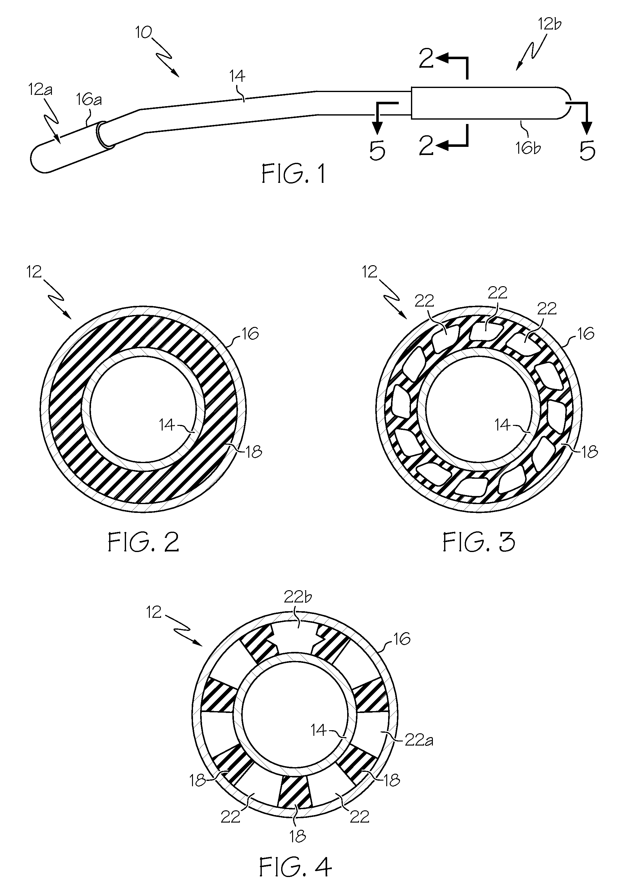
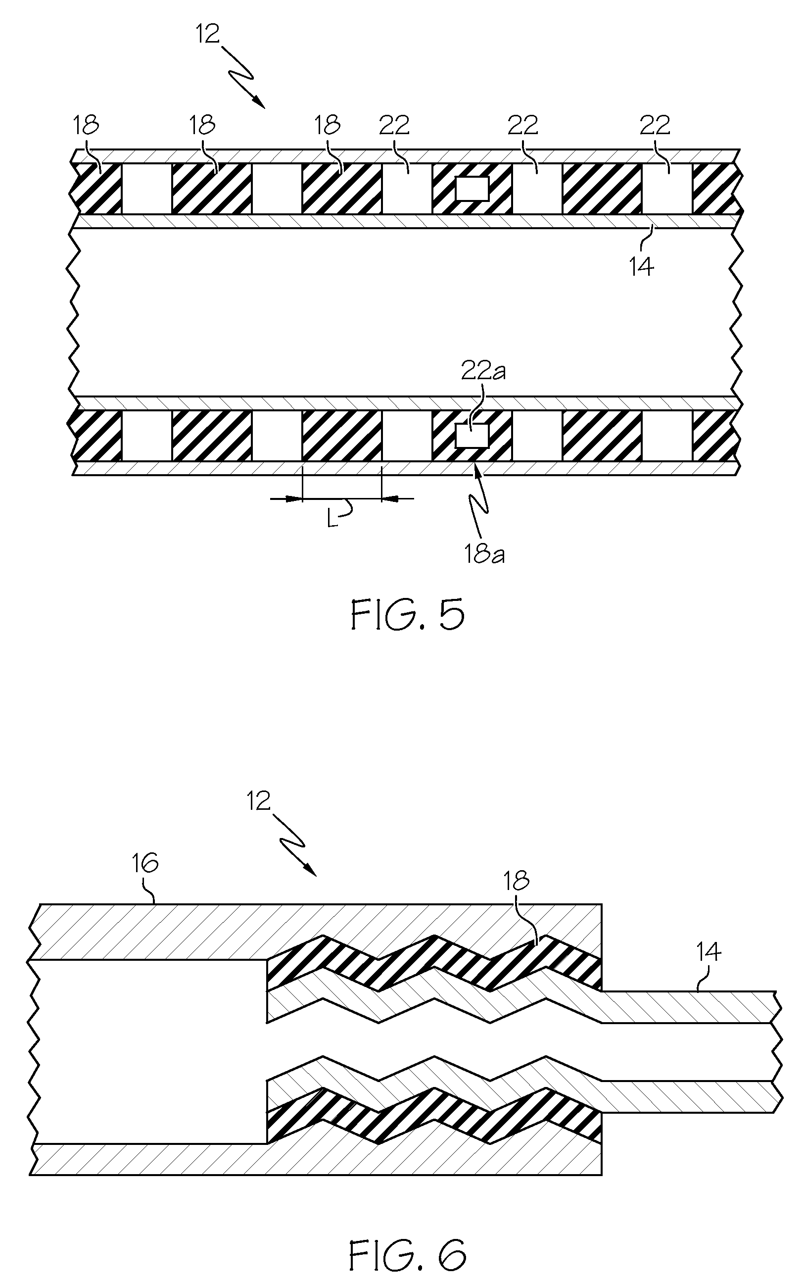
[0026]The invention is directed to devices 8 that are subject to vibration during use and have at least one dampening portion 12. Examples of devices 8 that are subject to vibration during use, include, but are not limited to, bicycles, motorcycles, all terrain vehicles, personal watercrafts, lawn mowers, snowblowers, hedge trimmers, chain saws, blowers, jack hammers, axes, hammers, sport rackets for tennis and squash, and the like. Other devices 8 which can have at least one dampening portion 12 are discussed in U.S. Pat. Nos. 6,257,220; 6,382,301; ...


PUM


Abstract

A vibrating device has at least one dampening portion. The dampening portion comprises a first tube, a second tube and a layer of resilient material configured so that the first tube is disposed about the second tube, and the layer of resilient material is positioned between the first and second tubes.

Description

FIELD OF THE INVENTION[0001]This invention relates to dampening the vibrations felt by the user of devices such as bicycles, motorcycles, all terrain vehicles, personal watercrafts, lawn mowers, snowblowers, hedge trimmers, chain saws, blowers, jack hammers, axes, hammers, tennis rackets and the like. At least one region of the device is constructed and arranged to reduce the vibrations felt by the user of a vibrating device.BACKGROUND OF THE INVENTION[0002]Many recreational and work devices transmit vibrations to the user. Most of the time, the majority of vibrations are transmitted to the user's hands and arms when they are holding the device. These vibrations can cause fatigue and discomfort during use and, in some cases, prolonged use of these devices can cause pain or injury to the user. Therefore, it is desirable to reduce the amount of vibrations transmitted to the user.[0003]U.S. Pat. Nos. 6,257,220 and 6,382,301 to McPherson et al. discuss vibration dampers as applied to ar...

Claims


Application Information

Patent Timeline
IPC IPC(8): F16M13/00
CPCF16L9/21
Inventor MCPHERSON, MATHEW A.
Owner MCP IP
Why Eureka
Try Eureka