Communication apparatus, communication method, and computer program for controlling communication apparatus

a communication apparatus and computer program technology, applied in home automation networks, digital transmission, data switching networks, etc., can solve the problems of printers not being able to always accept print instructions, printers not being able to describe physical connection/disconnection between printers and communication adapters, and upnp not defining a determination criterion

Inactive Publication Date: 2009-03-19
CANON KK
View PDF31 Cites 20 Cited by
  • Summary
  • Abstract
  • Description
  • Claims
  • Application Information

AI Technical Summary

Benefits of technology

[0016]For example, the feature of the present invention is to prevent issuing a service request to an electronic apparatus incapable of providing a service, when the communication apparatus is connected to the electronic apparatus for providing a predetermined service. Another feature of the present invention will be apparent from the following specification and accompanying drawings.

Problems solved by technology

However, UPnP does not define a determination criterion for determining if a device joins the logical network or not, and if it leaves from it or not.
When the DSC with the wireless communication function instructs the printer connected to the communication adapter to print, the printer cannot always accept a print instruction even if the DSC is wirelessly connected to the communication adapter.
However, the above-described prior art does not describe physical connection / disconnection between the printer and the communication adapter.
Even if the communication adapter is connected to a partner device (e.g. the DSC) via a network, the printer cannot provide a print service when the communication adapter is not connected to the printer.
Even if the communication adapter is connected to the printer, the printer cannot provide a print service when the status of the printer is not suited to provide the print service.
Accordingly, even if the communication adapter notifies, based on the connection status with the network, a device that the printer joins the network, the device which has received the notification cannot always use a print service in practice.
Such problem occurs not only when the communication adapter is to be connected to the printer, but also when various devices such as a scanner and monitoring camera capable of remote control are to be used.

Method used


Image

  • Communication apparatus, communication method, and computer program for controlling communication apparatus
  • Communication apparatus, communication method, and computer program for controlling communication apparatus
  • Communication apparatus, communication method, and computer program for controlling communication apparatus

Examples


first embodiment

[0046]In the first embodiment, a system in which a communication adapter is connected to a printer for providing a print service to a DSC with a wireless communication function will be described.

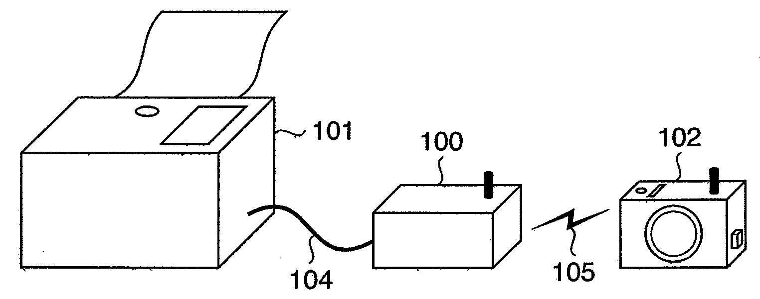
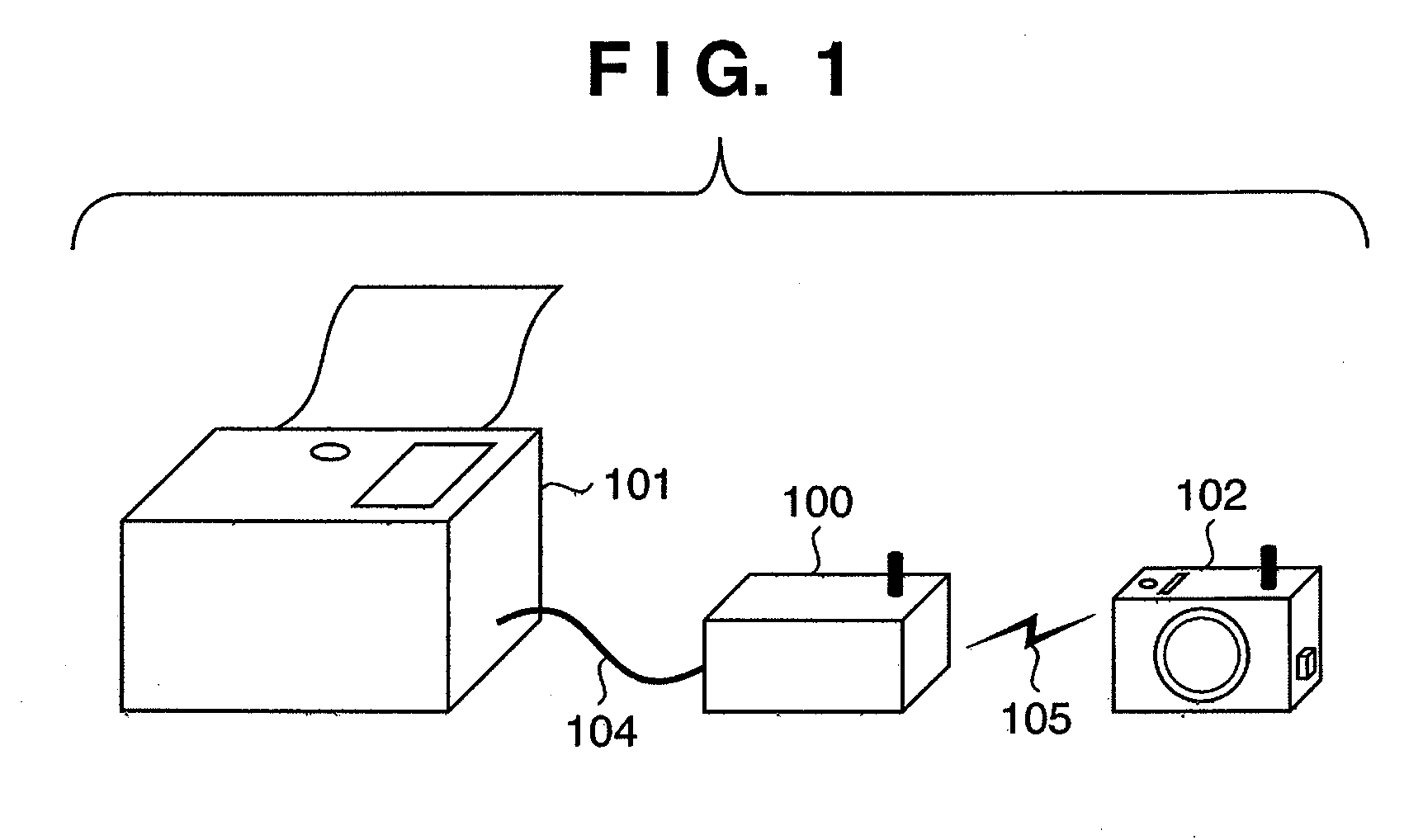
[0047]FIG. 1 is a system diagram according to the first embodiment. A communication adapter 100 is connected to a printer 101 via a USB cable 104. The communication adapter 100 is also connected to a DSC 102 via a wireless LAN 105. Although not shown, the communication adapter 100 installs UPnP as a function for searching for a device and a service. A print service from the printer 101 is relayed via the communication adapter 100 to the DSC 102.

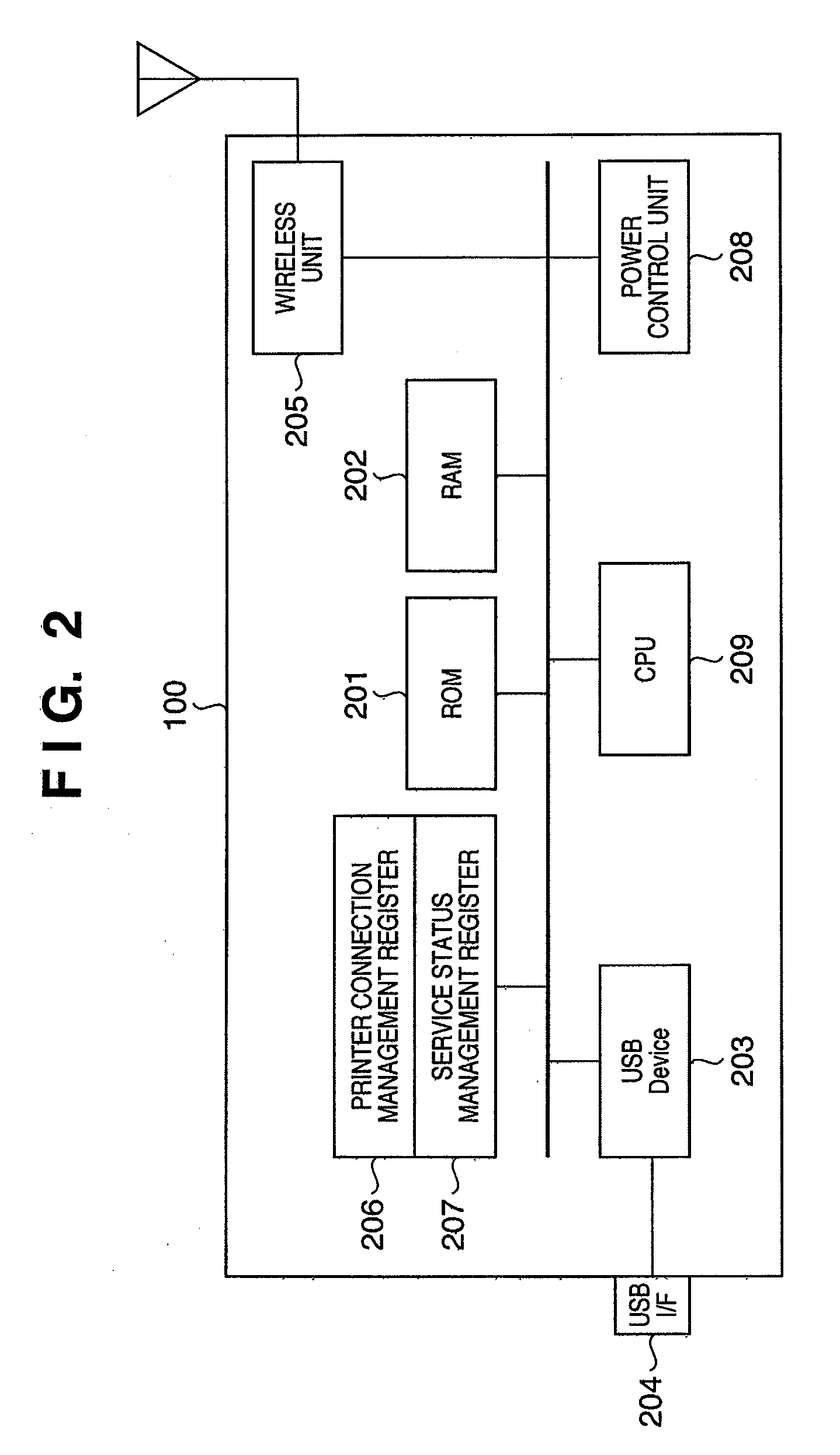
[0048]FIG. 2 is a schematic view of the communication adapter 100 according to the first embodiment. A ROM (Read Only Memory) 201 stores an operation program and the like for operating the communication adapter 100 (to be described later). A RAM (Random Access Memory) 202 serves as a work memory and an area for expanding the operation program. A USB (...

second embodiment

[0060]In the second embodiment, a communication adapter 100 includes a wireless LAN connection management register in addition to a printer connection management register 206 and a service status management register 207.

[0061]A CPU 209 asynchronously controls a USB device controller 203 and a wireless unit 205. Hence, wireless LAN connection via the wireless unit 205 and USB connection with the printer 101 via the USB device controller 203 are independently established. Accordingly, even in a state wherein a DSC 102 is not within a communication range, or wherein the DSC 102 is not powered on, the communication adapter 100 may be connected to the printer 101 via the USB.

[0062]Even after establishing the wireless connection between the DSC 102 and the communication adapter 100, the wireless LAN may be disconnected when radio wave signals become weaker.

[0063]The wireless LAN connection management register is arranged in order to prevent, when the wireless LAN is disconnected, a softwa...

third embodiment

[0071]In the first and second embodiments, the communication adapter 100 transmits the “Alive” or “Bye-Bye” signal when the communication adapter 100 is connected / disconnected to / from the printer 101 via the USB cable 104. However, in a case where an error such as a paper jam or ink shortage occurs, the printer 101 cannot print even if it is connected to the communication adapter 100. Therefore, in the third embodiment, a communication adapter 100 transmits an “Alive” or “Bye-Bye” signal in accordance with the error status of a printer in addition to the status of whether or not the printer is connected to the communication adapter.

[0072]In the third embodiment, upon detecting the connection between the communication adapter 100 and the printer 101 as in the first and second embodiments (YES in step S304 in FIGS. 3 and 9), one process is added to be performed. Upon detecting the connection with the communication adapter 100, the-printer 101 transmits its error status to the communic...


PUM


Abstract

In a system in which a communication adapter installing UPnP is connected to a printer to provide a print service, the communication adapter notifies a device that the printer joins the network or leaves from it, based on determination whether the printer can provide a service. Hence, the present invention can suppress from issuing a service request to a printer which cannot provide the service.

Description

TECHNICAL FIELD[0001]The present invention relates to a communication apparatus to be connected to a first electronic apparatus, a communication method, and a computer program for controlling the communication apparatus.BACKGROUND ART[0002]UPnP (Universal Plug and Play) is standardized as a technical specification for connecting devices such as a PC and peripheral equipment in home via a network to provide their functions to each other.[0003]In recent years, wireless communication is performed via a wireless LAN or the like to connect a printer, digital still camera (to be referred to as a DSC hereinafter), PC, and the like. For example, a service is proposed in which, upon connecting a communication adapter to a printer, a DSC with a wireless communication function can instruct, by wireless communication, the printer to print. UPnP can also be applied to such service.[0004]UPnP defines that a device transmits an “Alive” message when it joins a logical network, and a device transmit...

Claims


Application Information

Patent Timeline
Patent Type & Authority Applications(United States)
IPC IPC(8): H04B7/00
CPCH04L12/2803H04L12/2809H04L2012/2841H04N2201/0084H04N2201/0015H04N2201/0055H04N2201/0062H04N1/00278
Inventor SHICHINO, TAKAHIROHIROSE, TAKATOSHIYAMAMOTO, TETSUYANAGO, HIDETADASHIMURA, HAJIMEMASHIMO, HIROSHI
Owner CANON KK
Why Eureka
Try Eureka