Liquid jet surgical instruments incorporating channel openings aligned along the jet beam

a surgical instrument and jet beam technology, applied in the field of liquid jetforming surgical instruments, can solve the problems of inability to precisely control the depth of cutting and/or tissue ablation with the instrument, poor tissue differentiation capability, and inadvertent damage to tissue surrounding the surgical treatment site, etc., to achieve the effect of convenient control, improved accuracy and convenient operation

Active Publication Date: 2009-03-19
HYDROCISION
View PDF99 Cites 43 Cited by
  • Summary
  • Abstract
  • Description
  • Claims
  • Application Information

AI Technical Summary

Benefits of technology

[0006]Certain embodiments of the present invention provide a series of surgical instruments utilizing liquid jets for cutting, ablating, debriding, washing, etc., tissues and / or other materials from the interior and / or external surface of the body of a patient. Certain embodiments of the liquid jet surgical instruments provided according to the invention utilize a channel positioned adjacent to and downstream of a liquid jet-forming nozzle such that at least a portion of the liquid jet passes at least one of within the channel and adjacent to and along the length of at least a portion of a longitudinally-oriented opening in the channel, when the instrument is in operation. As explained in more detail below, the use of such channels in certain embodiments of the inventive liquid jet surgical instruments can enable the instruments to provide enhanced control over the depth and degree of cutting and / or ablation of tissue; and / or can provide improved and enhanced functionality for cleaning, debriding, and / or trimming and cutting a tissue surface; and / or can provide longer effective liquid jet beam cutting / ablation lengths by reducing the degree of dispersion of the jet along its length, especially for instruments utilized in a surrounding gaseous environment.
[0009]As explained in more detail below, in certain embodiments of the present invention, the liquid jet surgical instruments can include a channel positioned adjacent to and downstream of a nozzle of the instrument such that at least a portion of the liquid jet passes within the channel and / or adjacent to and along the length of at least a portion of a tissue-facing opening of the channel, when the instrument is in operation. As explained below, the provision of such channel(s) in certain embodiments of the inventive instruments can provide and / or enhance at least one of, and in some embodiments many or all of, the beneficial functionalities discussed above and in more detail below.
[0011]The present inventors have discovered, in the context of the present invention, that certain additional functionalities of a liquid jet surgical instrument can be provided and certain operating properties of a liquid jet surgical instrument can be made, in certain instances, more readily controllable by providing liquid jet surgical instruments with components and / or structures enabling control of the location of the liquid jet beam with respect to the surface of the tissue to be treated and / or the surface of a tissue-contacting portion of the surgical instrument and / or by providing components and / or structures enabling the degree of dispersion of the liquid jet beam and / or the interaction of the jet beam with the surrounding environment to be reduced.
[0012]In some embodiments, the liquid jet instruments provided according to the invention can include a channel at least partially surrounding and / or adjacent to at least a portion of the jet beam, which channels can include tissue-contacting portions comprising opening(s) therein of particular sizes and shapes. The sizes and / or shapes of such openings, in some embodiments, can be specifically configured to affect certain performance parameters such as the degree and extent of cutting of the tissue by the instrument, the size and shape of the tissue treatment zone, the degree of suction created by the instrument between the tissue-contacting surface and the tissue, etc. In some embodiments, the instruments provided according to the invention provide new and useful functionalities, such as those described above, and, in particular, in certain embodiments the instruments can be made easier for an operator to control and / or can be made to be more precise with regard to the depth and area of tissue removed by the instrument, and / or can be configured to selectively allow for tissue cutting, washing, or both. In some embodiments, the instruments can be further configured to allow for reproducible variation of one or more of the above-described parameters by a user of the instrument during use, and in certain particular embodiments, intraoperatively.

Problems solved by technology

Traditionally, many surgical procedures for both open surgery and minimally invasive surgery (i.e., endoscopic, laparoscopic, or arthroscopic surgical procedures) have utilized surgical tools such as scalpels, scrapers, blunt dissectors, lasers, electrosurgical devices, etc., which can have poor tissue differentiating capability, which may easily cause inadvertent damage to tissue surrounding a surgical treatment site, and which do not typically provide for an ability to precisely control a depth of cutting and / or tissue ablation with the instrument and / or effectively provide for evacuation from the treatment site of cut / ablated tissue.
Many such surgical procedures can entail more extensive trauma to the patient and / or require longer operating procedures, with associated problems of long recovery periods and potential complication, than is desirable.

Method used


Image

  • Liquid jet surgical instruments incorporating channel openings aligned along the jet beam
  • Liquid jet surgical instruments incorporating channel openings aligned along the jet beam
  • Liquid jet surgical instruments incorporating channel openings aligned along the jet beam

Examples


first embodiment

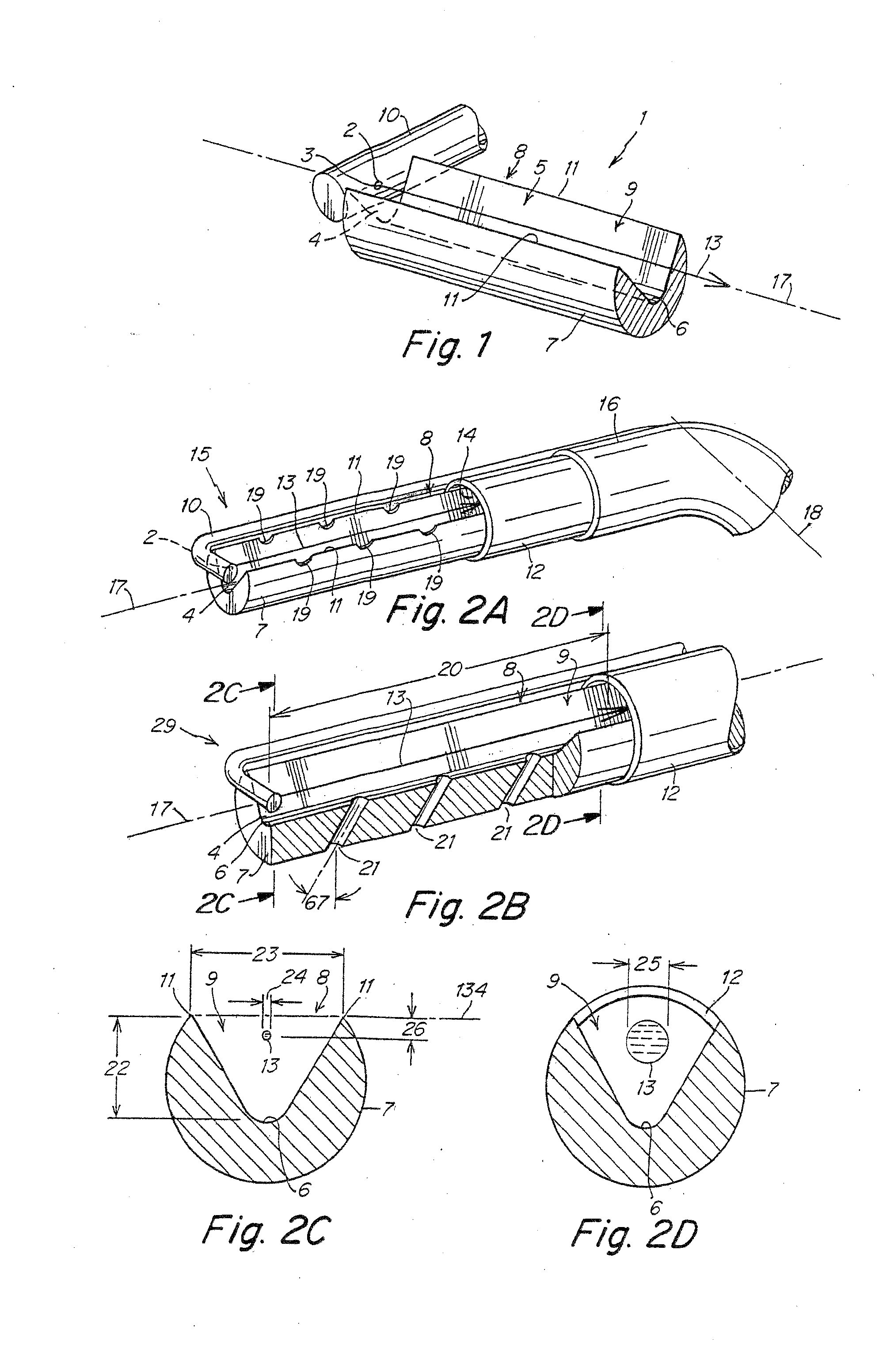
[0068]FIG. 1 illustrates a jet tip 1 provided at the distal end of a surgical instrument according to one embodiment of the invention. A pressure lumen 10 is provided that is configured and positioned to conduct a liquid from the proximal end of the instrument (not shown) towards the distal end of the instrument. In the embodiment illustrated, the distal end of pressure lumen 10 is sealed and a nozzle 2 is formed in the sidewall of the lumen by, for example, drilling or etching. It should be noted that the illustrated configuration of the distal end of high pressure lumen 10 and the nozzle 2 is merely exemplary and that a wide variety of other techniques for forming the nozzle can be utilized. A number of such techniques, and exemplary nozzles formed thereby, which can be used in certain embodiments of the present invention, are described in detail in Applicants' U.S. Pat. No. 6,375,635.

[0069]In general, the nozzle can be formed in the high pressure lumen by any means known to those...

embodiment 15

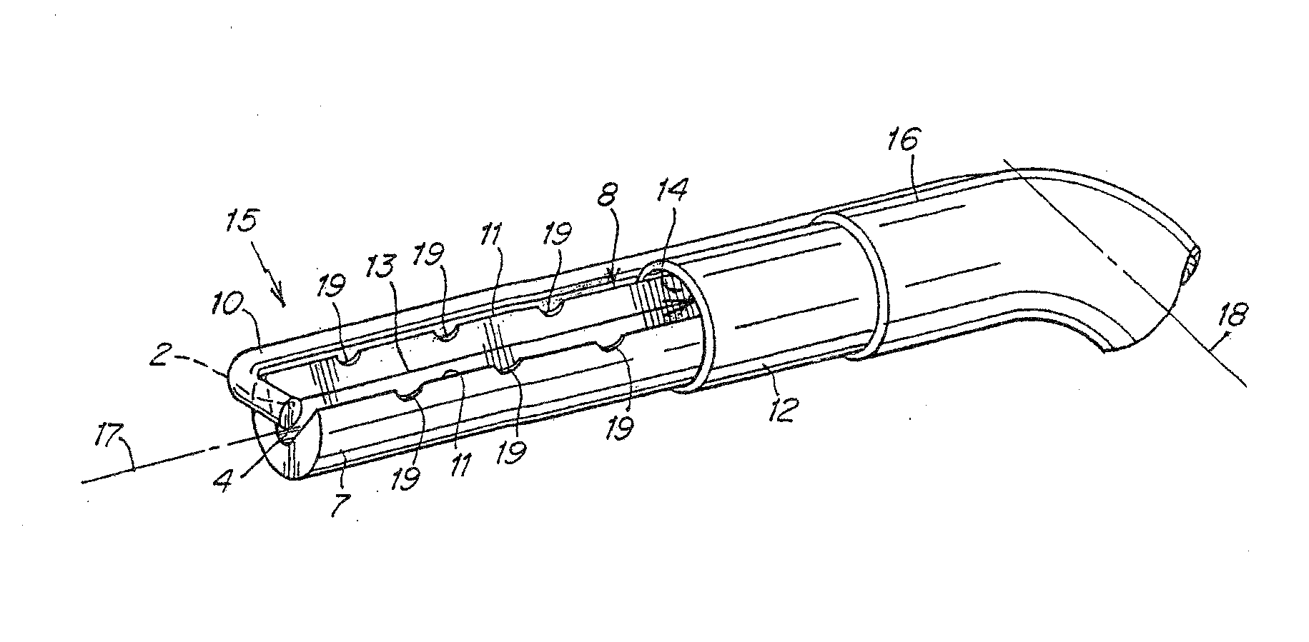
[0075]Various configurations of an entire jet tip for an embodiment of the invention providing the ability to evacuate liquid and debris from the surgical site are illustrated in FIGS. 2A-2D. These figures will be used to illustrate and discuss certain geometric relationships which can affect performance of the jet tip. In the embodiment 15 illustrated in FIG. 2A, high pressure lumen 10 is bent so that its distal end forms approximately a right angle with the longitudinal axis 17 of the jet tip so that the liquid jet 13 emitted by nozzle 2 passes within channel 9 and travels down the longitudinal length of the channel. The distal end of the high pressure lumen 10 does not fully occlude the inlet face 4 of channel 9 leaving an open aperture therein providing a vent aperture. While the axially-oriented jet tip configuration of jet tip 15 is illustrated as a particular example herein, it should be understood that in alternative embodiments other geometric configurations and relative or...

embodiment 41

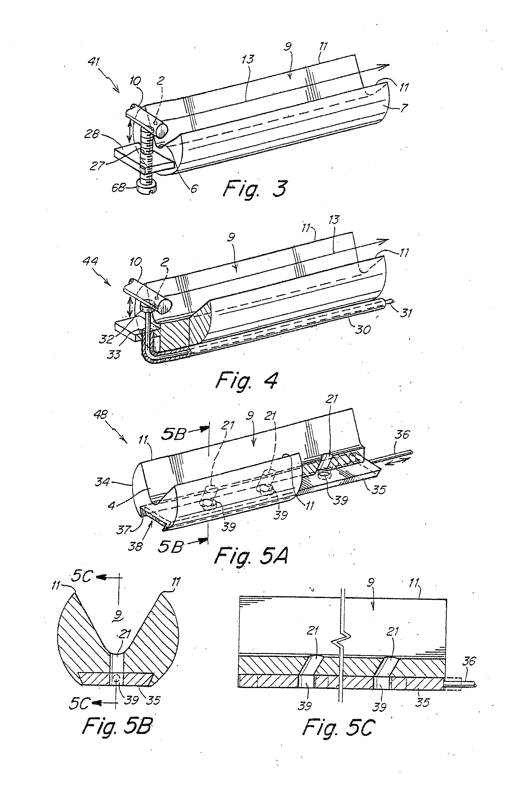
[0094]In one such embodiment, illustrated in FIGS. 3 and 4, a surgical instrument can be provided with a jet tip allowing the beam height to be varied. In the jet tip embodiment 41 illustrated in FIG. 3, adjustment of the beam height can be effected through the use of the set screw 26 configured to be in contact with, and, alternatively, attached to high pressure lumen 10. Set screw 26 is threaded through a threaded hole 27 in a distal extension 28 of the component 7 forming the channel 9. Set screw 26 acts on high pressure tubing 10 when turned, thereby displacing nozzle 2 with respect to channel 9, thus altering the beam height of jet beam 13. Thus, turning the set screw 26 can increase or decrease the beam height of the jet beam by displacement of the distal end of the high pressure tube. As would be apparent to those of ordinary skill in the art, various other means could alternatively be used to vary the beam height of the jet within or adjacent to the channel, each of which wo...


PUM


Abstract

Certain embodiments of the surgical instruments provided according to the invention utilize a channel positioned adjacent to and downstream of a liquid jet-forming nozzle such that at least a portion of the liquid jet passes at least one of within the channel and adjacent to and along the length of at least a portion of a longitudinally-oriented opening in the channel, when the instrument is in operation. The use of such channels in certain embodiments of the inventive surgical instruments can enable the instruments to provide enhanced control over the depth and degree of cutting and / or ablation of tissue; and / or can provide improved and enhanced functionality for cleaning, debriding, and / or trimming and cutting a tissue / surface; and / or can provide longer effective liquid jet beam cutting / ablation lengths by reducing the degree of dispersion of the jet along its length.

Description

RELATED APPLICATIONS[0001]This non-provisional application is a divisional application of U.S. application Ser. No. 10 / 302,766, filed Nov. 21, 2002, which claims the benefit under Title 35, U.S.C. § 119(e) of U.S. provisional application Ser. No. 60 / 332,156, filed Nov. 21, 2001, the entire content of each application is incorporated herein by reference.FIELD OF THE INVENTION[0002]This invention relates to liquid jet-forming surgical instruments for cutting, ablating, lavage, and similar treatments of a tissue of a patient during a surgical or medical procedure.BACKGROUND[0003]Traditionally, many surgical procedures for both open surgery and minimally invasive surgery (i.e., endoscopic, laparoscopic, or arthroscopic surgical procedures) have utilized surgical tools such as scalpels, scrapers, blunt dissectors, lasers, electrosurgical devices, etc., which can have poor tissue differentiating capability, which may easily cause inadvertent damage to tissue surrounding a surgical treatme...

Claims


Application Information

Patent Timeline
Patent Type & Authority Applications(United States)
IPC IPC(8): A61M1/00A61B17/32
CPCA61B17/3203
Inventor MOUTAFIS, TIMOTHY E.FREEMAN, JR., DONALD C.BROMANDER, EDWARD
Owner HYDROCISION
Why Eureka
Try Eureka