Flexible Exhaust Pipe Coupling

Inactive Publication Date: 2009-03-26
VOLVO TRUCKS NORTH AMERICA
View PDF13 Cites 1 Cited by
  • Summary
  • Abstract
  • Description
  • Claims
  • Application Information

AI Technical Summary

Benefits of technology

[0001]The invention relates to exhaust systems for vehicles, in particular heavy trucks. More particularly, the invention relates to a flexible coupling for an exhaust system for a heavy truck that allows liquid to pass through the coupling without leakage.
[0005]The present invention provides a flexible pipe coupling system that eliminates components and associated cost and complexity of known devices, while providing a coupling allowing liquid to pass without leakage.
[0008]According to another aspect of the invention, an outlet of the guide tube may include a radially outwardly flaring mouth to improve the pressure loss at the outlet of the guide tube.
[0009]According to another aspect of the invention, an inlet end of the downstream pipe may be shaped with a rim that converges radially inwardly. The rim of the downstream pipe helps prevent backflow of liquid into the flexible sleeve area.
[0011]The invention provides a low cost, reliable device. The flexible sleeve allows the upstream exhaust pipe and downstream exhaust pipe to move relative to one another, but the sleeve does not need to be liquid tight. The internal guide tube carries liquid and exhaust gas flow through the coupling joint without leakage.

Problems solved by technology

The pipes are subject to vibrations from the flowing gases and vibrations and bending movements imparted by the moving vehicle.

Method used


Image

  • Flexible Exhaust Pipe Coupling
  • Flexible Exhaust Pipe Coupling
  • Flexible Exhaust Pipe Coupling

Examples


Embodiment Construction

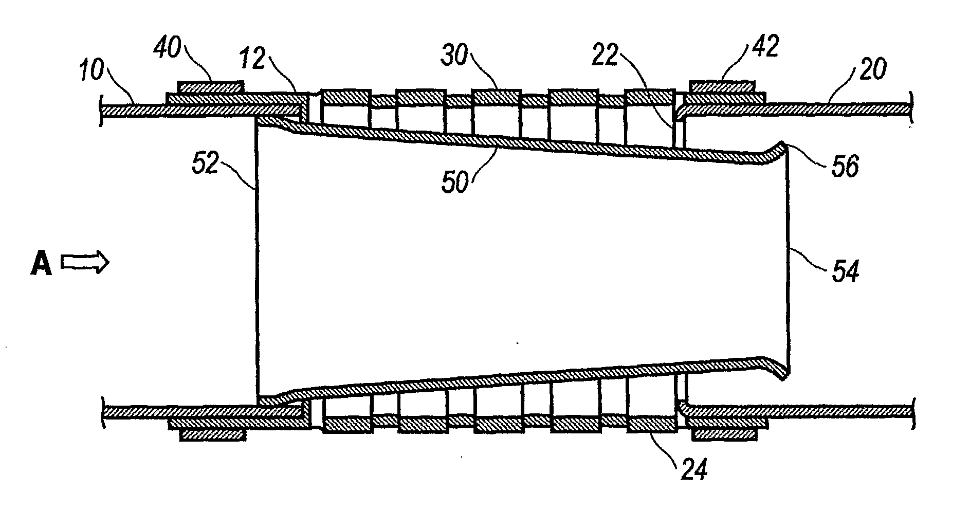
[0019]FIG. 1 shows a longitudinal sectional view of an exhaust pipe coupling device in accordance with a first embodiment of the invention. The device connects an upstream exhaust pipe 10 with a downstream exhaust pipe 20. The normal flow direction of exhaust gas is shown by arrow A. In addition to carrying gas combustion products, truck exhaust systems are or may in the future be called on to carry liquid material to treat the combustion products or to clean or regenerate exhaust after-treatment devices, such as diesel particulate filters, oxidizers, or catalyzers. The liquid material may be as a condensate or atomized form, and may include automotive or diesel fuel, urea, ammonia, or some other combustive, oxidizing or catalyzing agent. The device according to invention assures that liquid material passes the joint areas in the exhaust piping without leakage.

[0020]A flexible sleeve 30 receives the outlet end 12 of the upstream pipe 10 and the inlet end 22 of the downstream pipe 20...


PUM


Abstract

A device for connecting pipes in a heavy truck exhaust system includes a flexible sleeve joined to both connecting pipes and a flow guide connected or formed to an upstream pipe and extending through the flexible sleeve into the downstream pipe. The flow guide may have a frustoconical shape converging toward an outlet end with an outlet rim that flares radially outward. An inlet rim of the downstream pipe converges radially inward to prevent backflow into the joint region.

Description

BACKGROUND AND SUMMARY OF THE INVENTION[0001]The invention relates to exhaust systems for vehicles, in particular heavy trucks. More particularly, the invention relates to a flexible coupling for an exhaust system for a heavy truck that allows liquid to pass through the coupling without leakage.[0002]Exhaust systems in truck tractors conduct exhaust gases along a relatively long path from the engine rearward of the cab to a stack or tail pipe. The pipes are subject to vibrations from the flowing gases and vibrations and bending movements imparted by the moving vehicle. To accommodate vibration and flexing, the pipe joints are joined with resilient, movable couplings.[0003]U.S. Pat. No. 5,145,215 to Udell shows one such resilient coupling. The device includes two sleeve members 16, 17 that join in an overlapping manner. The end edges of the sleeves are turned outward and inward, respectively, to retain a spacer member 48 between the sleeves. The sleeves are surrounded by a bellows 10...

Claims


Application Information

Patent Timeline
IPC IPC(8): F01N7/00F01N13/18
CPCF01N13/1816F01N2590/08F01N2470/30F01N2470/12
Inventor LANGERVIK, DENNIS
Owner VOLVO TRUCKS NORTH AMERICA
Why Eureka
Try Eureka