Wide-range float type flow sensor

A flow sensor, float-type technology, applied in the field of wide-range float-type flow sensor devices, to achieve the effect of simple structure, low cost, and wide range

Inactive Publication Date: 2009-05-06
王永忠
View PDF4 Cites 1 Cited by
  • Summary
  • Abstract
  • Description
  • Claims
  • Application Information

AI Technical Summary

Problems solved by technology

There is a V-shaped drainage hole on both sides of the top of the duct

Method used


Image

  • Wide-range float type flow sensor
  • Wide-range float type flow sensor
  • Wide-range float type flow sensor

Examples


Embodiment Construction

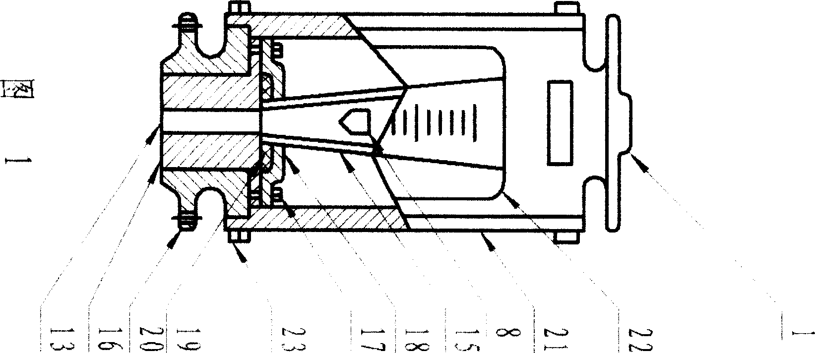
[0013] In FIG. 1 : the float 8 is placed in the conical tube 15 , the conical tube 15 is combined with the insert 16 , and the compression cover 18 together with the sealing ring 19 is fixed on the base 20 by the screw 17 . The support plate 21 and the casing 22 are connected to the base 20 by screws 23 .

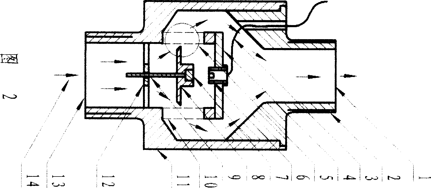
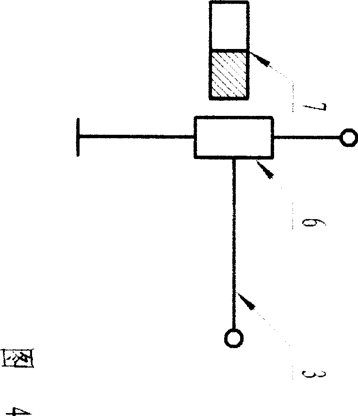
[0014] In Fig. 2: the float guide tube 10 is connected with the sensor lower housing 11, the guide bracket 12 is connected with the inner wall of the guide tube 10, the guide rod 9 is fixedly connected with the center position below the float 8, and the magnet 7 is fixed above the float 8 The center position, and corresponds to the center of the Hall probe 6. When assembling, the float should move up and down flexibly. During manufacture, the upper and lower housings 2 and 11 and the draft tube 9 are circular, the float 8 is a circular sheet, and the guide rod 9 is made of stainless steel material. Probe Hall SS495 market procurement parts. Assemble in the order of insid...


PUM


Abstract

A new sensor applied for flow measurement field, is wider measurement range, simple structure, and fewer parts. In the sensor's shell, the sensor probe is a Hall sensitive part, installed in the center of the top lid of the flow-guide pipe, corresponding to the magnet body above the floater, and the floater is a round-flake style, the guide rod fixed in the center position of the floater, and through the stand of the floater's flow-guide pipe, the floater maintaining a balance when displaces from top to bottom. The both sides of the top of the flow-guide pipe respectively have a drainage whole, upside and downside respectively having an export and import. When measured fluid flowing, the magnet body linked with the floater produces the corresponding displacement, making the Hall probe export the corresponding changing electric signal. The mini sensor can keep the low cost, while greatly optimize the technical targets of the flow sensor on range, precision, pressure loss, pressure resistance, etc., and achieve and some better than the existing national industry standards. When applied to civilian gas meter, it can achieve the sensing, transmission, intelligent integration of the smart gas meters in the real sense.

Description

Technical field: [0001] The invention relates to a wide range float type flow sensing device capable of detecting gas and liquid flow. Background technique: [0002] At present, the known structure of the float flowmeter is composed of a base, a sign, a casing, a float, a tapered pipe, a support plate, a compression cover, a sealing ring, a bolt, an insert, and assembly. When the measured fluid passes through the annular gap formed by the tapered tube and the float from bottom to top, the upper and lower ends of the float will generate differential pressure to form the thrust of the float rising. As the area increases, the fluid velocity at the annulus drops immediately, the differential pressure at the upper and lower ends of the float decreases, and the upward thrust acting on the float also decreases, until the upward thrust is equal to the weight of the float immersed in the fluid, the float will stabilize at a certain value a height. At the same time, the calibration ...

Claims


Application Information

Patent Timeline
Patent Type & Authority Patents(China)
IPC IPC(8): G01F1/52
Inventor 王永忠
Owner 王永忠
Why Eureka
Try Eureka