Transmitter and receiver gain calibration by means of feedback in a transceiver

a transceiver and feedback technology, applied in the direction of transmitter monitoring, receiver monitoring, transmission monitoring, etc., can solve the problems of high linearity, exceedingly difficult to achieve without calibration, and inability to fabricate the transceiver, so as to achieve accurate gain calibration, accurate absolute gain, and low distortion

Active Publication Date: 2007-06-07
APPLE INC
View PDF3 Cites 47 Cited by
  • Summary
  • Abstract
  • Description
  • Claims
  • Application Information

AI Technical Summary

Benefits of technology

[0027] According to thirteenth feature of the invention, the steps of changing the gain parameter, measuring the at least one measurement, determining a relative effect and calibrating the gain step are iterated whereby calibration across a dynamic gain range is achieved. Thus an accurate absolute gain calibration can be performed at a reference signal level, and an accurate gain calibration can be achieved for an entire gain range using accurate relative gain measurements. Preferably the step of determining the relative effect is further in response to the relative effect determined in previous iterations.
[0028] According to a fourteenth feature of the invention, the signal level detector has a limited dynamic input range of low distortion and the reference signal level is set to fall within this dynamic range. This allows a simple and cheap construction of the signal level detector as accuracy is only required for a small range of values.
[0029] According to a second feature of the invention, there is provided an apparatus for gain calibration for a transceiver having a transmitter unit and a receiver unit and including a feed back coupling from the transmitter unit to the receiver unit, the feed back coupling comprising a measurement point; the apparatus comprising: a signal level measurement unit for measuring signal levels related to a feedback signal at the measurement point; the signal level measurement unit operable to be coupled to the measurement point through the receiver unit and/or through a signal level detector; means f

Problems solved by technology

With usual semiconductor technology, the transceivers cannot be fabricated such that the transmitted power levels have sufficient precision.
The circuit must measure the received power in 1 dB steps with ±5 dB precision (±8 dB at the ends of the range), which is exceedingly difficult to achieve without calibration.
Further due to the high peak to average value, OFDM requires high linearity over a wide dynamic range and meeting the requirements for the trans

Method used


Image

  • Transmitter and receiver gain calibration by means of feedback in a transceiver
  • Transmitter and receiver gain calibration by means of feedback in a transceiver
  • Transmitter and receiver gain calibration by means of feedback in a transceiver

Examples


Embodiment Construction

[0034] For clarity, the following description of a preferred embodiment of the invention focuses on the application in a HiperLAN2 transceiver, but it will be apparent that the invention is not limited to this application and can be used in a variety of transceivers requiring or benefiting from calibration.

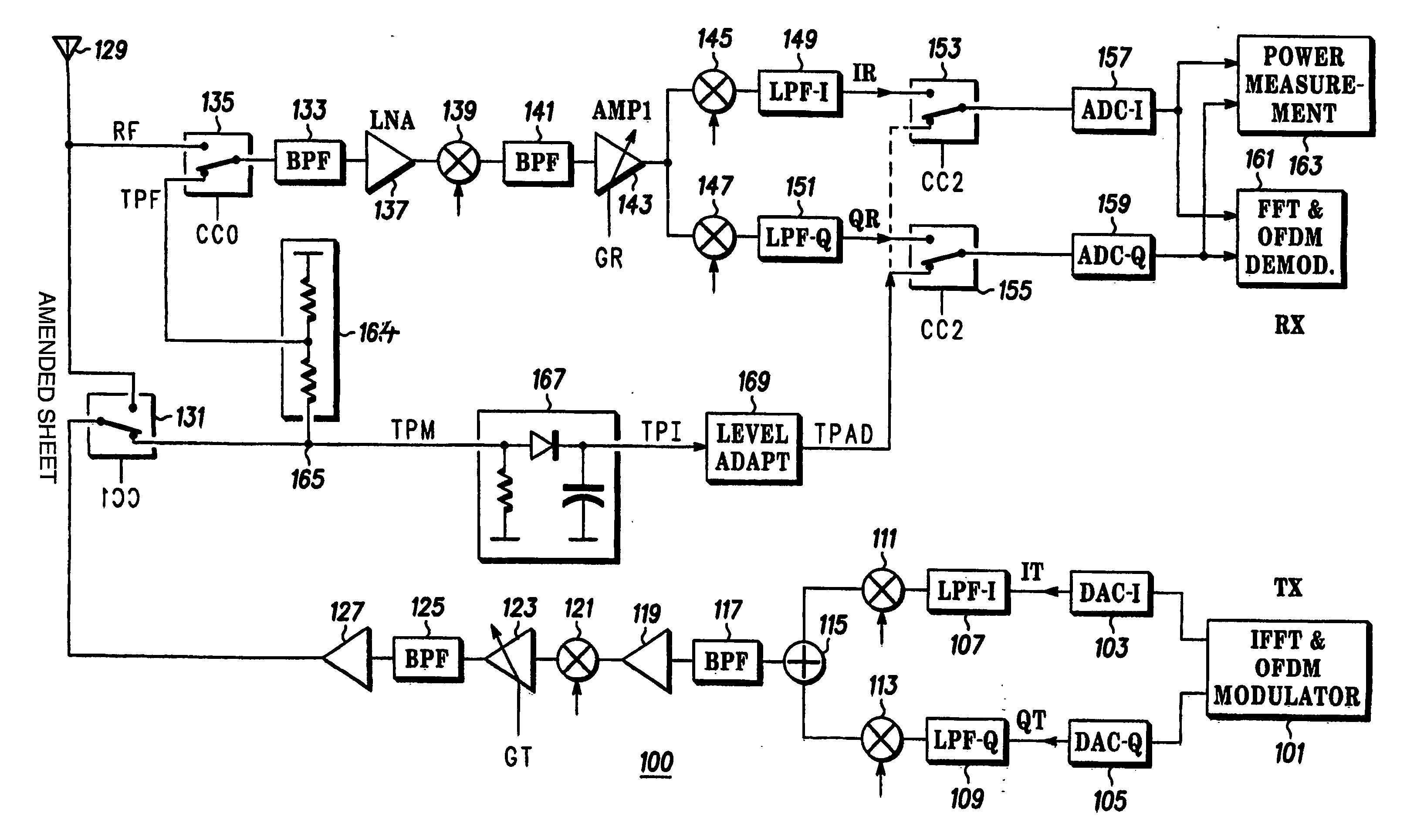
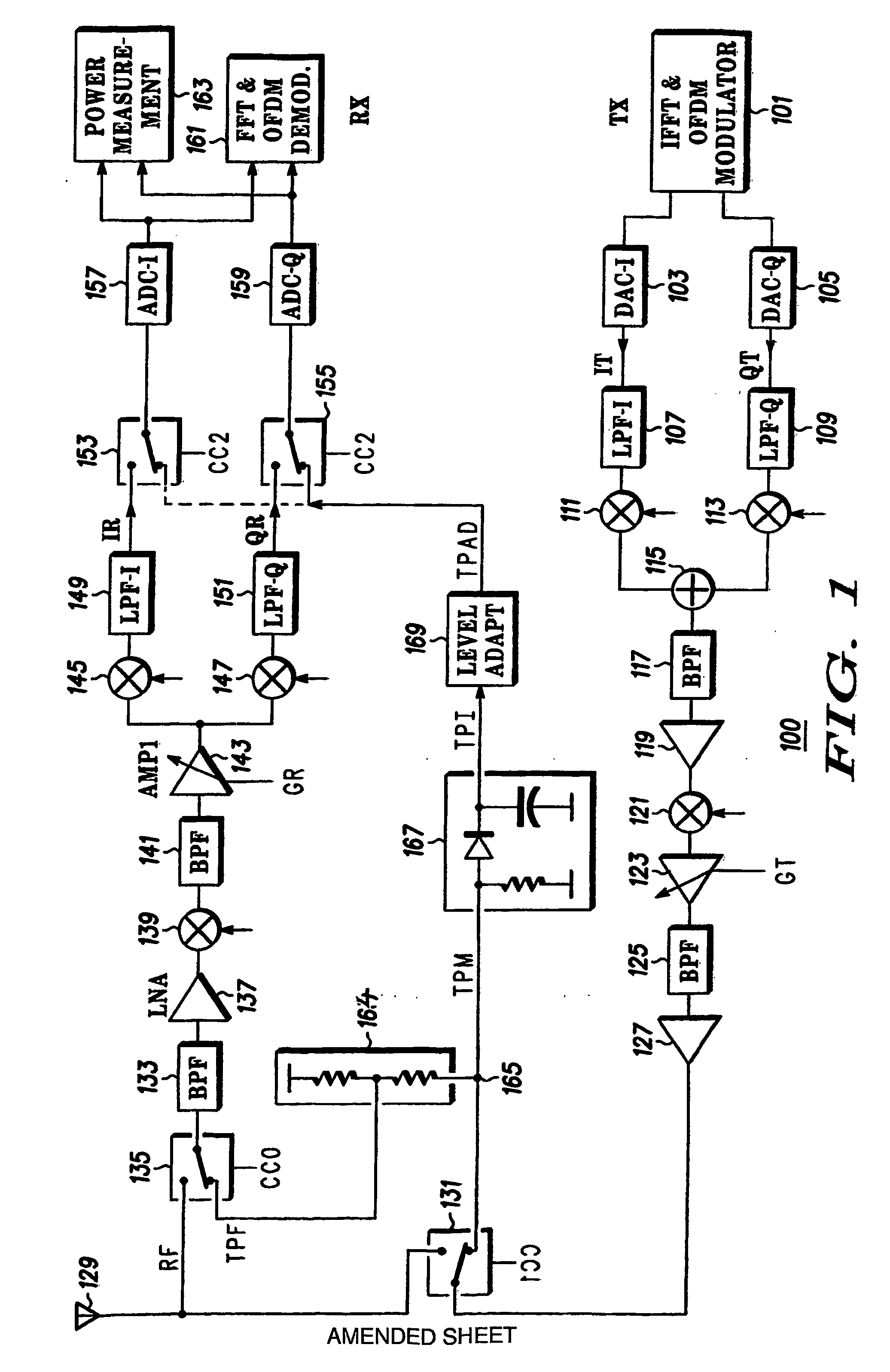
[0035]FIG. 1 is an illustration of a HiperLAN2 transceiver in accordance with a preferred embodiment of the invention.

[0036] A transmitter unit comprises a digital part and an analog part. The digital part comprises an Inverse Fast Fourier Transform (iFFT) 101 function for modulating a data stream to be communicated into a plurality of subchannels, as are well known for OFDM transmitters. The iFFT 101 is complex and produces an in-phase (I) and quadrature (Q) signal. Each of the I and Q signals are converted to analog signals in each of the two Digitial to Analog Converters (DAC) 103,105. The converted I and Q signals are low pass filtered in Low Pass Filters (LPF) 107, 109 to r...


PUM


Abstract

The invention relates to gain calibration in a transceiver unit (100) having a transmitter unit and a receiver unit and a feed back coupling (165) between these. A signal level measurement unit (163) measures signal levels of a feedback signal through either the receiver unit or through a signal level detector (167). A reference signal level of the feedback signal is set by adjusting the transmitter until the signal level measurement unit (163) measures a predefined value when connected through the signal level detector (167). An absolute value of the transmitter gain is then calibrated. The signal level measurement unit (163) is connected through the receiver unit and the absolute gain of the receiver is calibrated. A gain is changed either in the receiver or the transmitter unit. The relative signal level change of the feedback signal is measured and used to calibrate the gain step.

Description

FIELD OF THE INVENTION [0001] The invention relates to a method and apparatus for gain calibration and in particular for automatic calibration in a transceiver unit such as a HiperLAN transceiver. BACKGROUND OF THE INVENTION [0002] In recent years, increasing focus has been given to wireless communication between different communication and computational devices using Wireless Local Area Networks (WLANs). One such WLAN technology is High Performance Radio Local Area Network Type 2 (HiperLAN2), which has been standardised by the European Telecommunications Standards Institute (ETSI). HiperLAN2 enables wireless, communication of very high data rates (up to 54 Mbps) over short ranges. HiperLAN operates in the 5 GHz frequency range, uses Orthogonal Frequency Division Multiplex (OFDM) transmission techniques and supports different Quality of Service (QoS) for different connections. HiperLAN2 may thus carry different services including various data services, voice or video services. [0003...

Claims


Application Information

Patent Timeline
IPC IPC(8): H01Q11/12H04B1/06H04B1/04H04B1/40H04B17/00
CPCH04B1/40H04B17/14H04B17/318H04B17/24H04B17/20H04B1/10
Inventor NEWTON, ANTHONYLEHNING, HEINZ
Owner APPLE INC
Why Eureka
Try Eureka