Color wheel

a color wheel and wheel body technology, applied in the field of color wheels, can solve the problems of large stray light b, inside the projector,

Inactive Publication Date: 2009-03-26
HON HAI PRECISION IND CO LTD
View PDF14 Cites 7 Cited by
  • Summary
  • Abstract
  • Description
  • Claims
  • Application Information

AI Technical Summary

Benefits of technology

[0006]In accordance with one present embodiment, a color wheel for use in a DLP projector includes a rotating disk, a color filter, a sensor, and a processor. The rotating disk has two end surfaces, a circumferential side surface extending between the two end surfaces, and a timing mark arranged on the side surface thereof. The color filter is mounted on an end surface of the rotating disk for jointly rotating with the rotating disk, the color filter including a plurality of sector-shaped filter segments attached to one another. The sensor faces toward the side surface of the rotating disk and is configured for emitting a light beam toward the side surface of the rotating disk and detecting light beam reflected from the side surface of the rotating disk so as to determine a position of the timing mark relative to the color filter. The sensor has a casing defining a light inlet for receiving light reflected from the rotating portion. A shield is disposed around the light inlet of the sensor for preventing stray light coming into the sensor. The processor is electrically connected to the sensor for regarding the color index position of the color filter and drive a digital micromirror device corresponding to the rotation of the color filter.

Problems solved by technology

However, because light sources inside the projector usually provide very high intensity light beams, there will be a great deal of stray light 18 inside the projector.

Method used


Image

  • Color wheel
  • Color wheel
  • Color wheel

Examples


Embodiment Construction

[0010]Embodiments will now be described in detail below, with reference to the drawings.

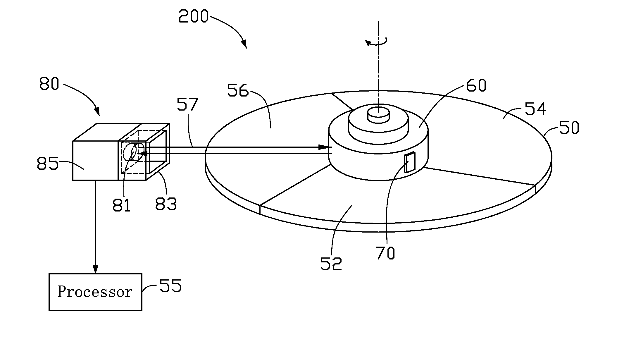
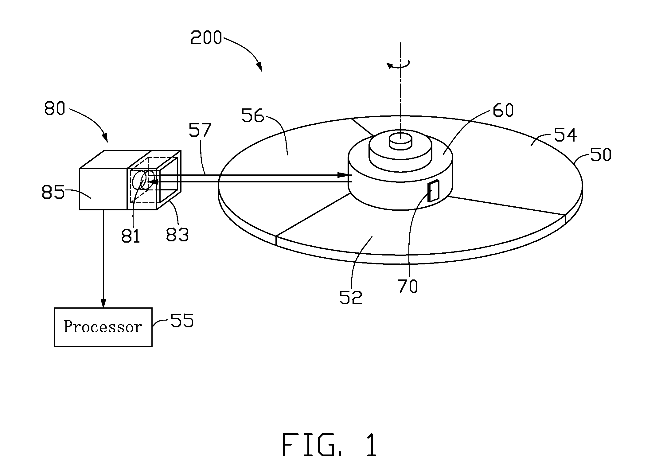
[0011]Referring to FIG. 1, a color wheel 200, in accordance with a present embodiment, includes a color filter 50, a motor (not shown) with a rotating disk 60, a processor 55, and a sensor 80. The sensor 80 is electrically coupled to the processor 55. The color wheel 200 is used in a digital light processing (DLP) projector (not shown) to separate light beams into three colors.

[0012]The color filter 50 has a transparent plate-configuration, beneficially, made from glass or quartz. The color filter includes a plurality of sector-shaped filter segments, such as a red filter segment 52, a green filter segment 54 and a blue filter segment 56. The contacting borders of the filter segments are adhered to one another by a glue and cooperatively form a through hole (not visible in FIG. 1) at the center thereof to facilitate mounting of the color filter 50 on the rotating disk 60, thereby the color filter...


PUM

PropertyMeasurementUnit
transparentaaaaaaaaaa
sizeaaaaaaaaaa
colorsaaaaaaaaaa

Abstract

A color wheel for use in a DLP projector includes a rotating disk, a color filter, a sensor, and a processor. The rotating disk has two end surfaces, a circumferential side surface extending between the two end surfaces, and a timing mark arranged on the side surface thereof. The color filter is mounted on an end surface of the rotating disk for jointly rotating with the rotating disk. The sensor faces toward the side surface of the rotating disk and is configured for determine a position of the timing mark relative to the color filter. The sensor has a casing defining a light inlet for receiving light reflected from the rotating portion. A shield is disposed around the light inlet of the sensor for preventing stray light coming into the sensor. The processor is electrically connected to the sensor for regarding the color index position of the color filter.

Description

TECHNICAL FIELD[0001]The present invention relates to the art of a color wheel and, particularly, to a color wheel in a projection display device.DESCRIPTION OF RELATED ART[0002]Referring to FIG. 2, a related color wheel 100 used in a digital light processing (DLP) projector (not shown) to separate light beams into three colors is provided. The color wheel 100 includes a rotating portion 20 of a motor (not shown), a color filter 10, a timing mark 40 adhered to the periphery of the rotating portion 20, a sensor 30 and a processor 25 electrically connected to the sensor 30.[0003]The color filter 10 comprises a red filter segment 12, a blue filter segment 14 and a green filter segment 16. In general, the color filter 10 is mounted on the rotating portion 20 and rotated together with the rotating portion 20. The timing mark 40 is configured to aid the sensor 30 to detect a color index position of the color filter 10 during rotation. When portions of light beams 17 from the sensor 30 are...

Claims


Application Information

Patent Timeline
Patent Type & Authority Applications(United States)
IPC IPC(8): G02F1/19G02B7/00
CPCG02B26/008
Inventor HUANG, KAI
Owner HON HAI PRECISION IND CO LTD
Why Eureka
Try Eureka