Oscilloscope digit fluorescence display method and control apparatus

A technology of digital fluorescence and display method, applied in the direction of digital variable display, digital variable/waveform display, measuring device, etc., can solve the problems of high component price and overall cost increase, so as to reduce interactive operations, improve efficiency, reduce cost effect

Active Publication Date: 2016-08-10
UNI TREND TECH (CHINA) CO LTD
View PDF6 Cites 11 Cited by
  • Summary
  • Abstract
  • Description
  • Claims
  • Application Information

AI Technical Summary

Problems solved by technology

[0006] In view of the above deficiencies, the object of the present invention is to provide an oscilloscope digital fluorescent display method and its control device, to solve the problem that the cost of the components used in the existing oscilloscope digital fluorescent implementation is high, leading to an increase in the overall cost

Method used


Image

  • Oscilloscope digit fluorescence display method and control apparatus
  • Oscilloscope digit fluorescence display method and control apparatus
  • Oscilloscope digit fluorescence display method and control apparatus

Examples


Embodiment 1

[0038] Please refer to figure 2 , the present embodiment provides an oscilloscope digital fluorescent display method, comprising the following steps:

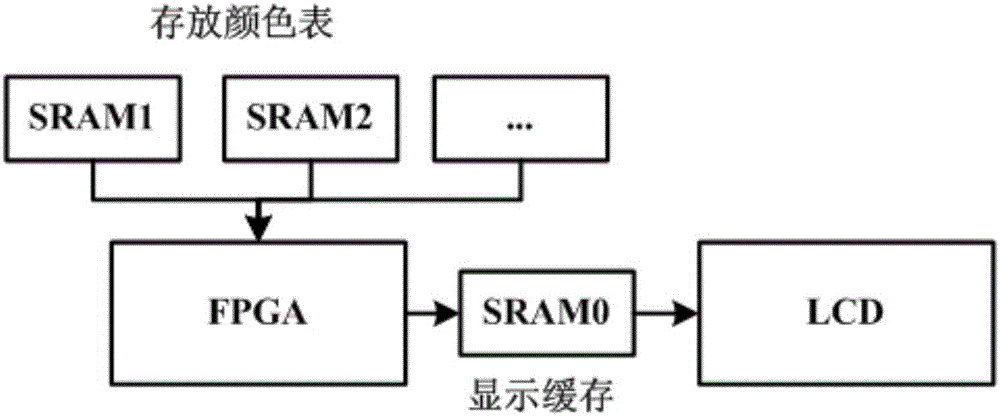
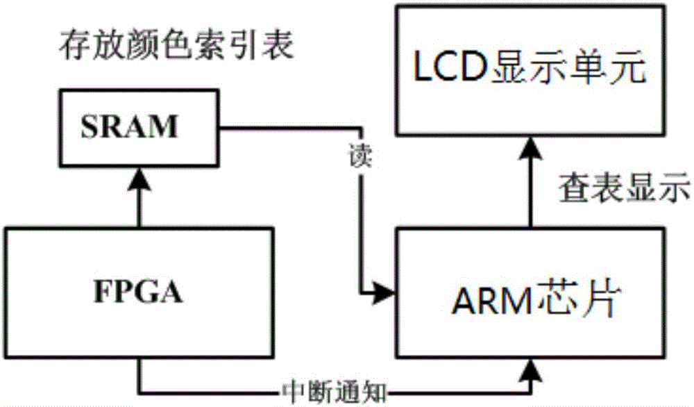
[0039] (1) A control device is preset in the oscilloscope, and the control device includes an FPGA (Field Programmable Logic Gate Array), an SRAM (Static Random Access Memory), an ARM chip and an LCD display unit;

[0040](2) Pre-store the color index table of each local channel in the ARM chip, the color index table includes several horizontal basic units and several vertical basic units, and the horizontal basic units and vertical basic units respectively include display point positions (X , Y), channel number and color index value, each color index value corresponds to a 24-bit color information;

[0041] (3) The FPGA continuously collects electrical signals at high speed, receives data and generates drawing data, then the FPGA transmits the drawing data to the SRAM, the SRAM receives the drawing data, generates and stores...

Embodiment 2

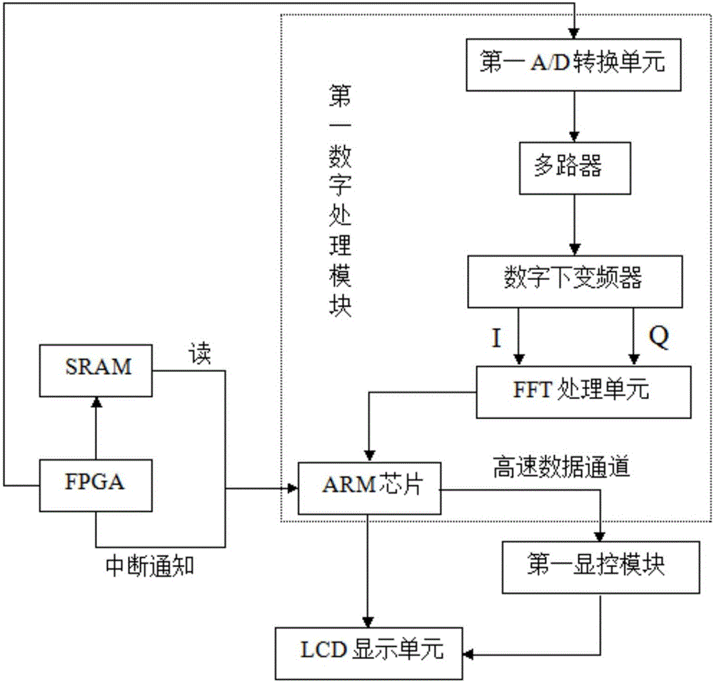
[0048] Please refer to image 3 , the main difference between this embodiment and Embodiment 1 is:

[0049] In the step (1), the control device further includes a first digital processing module and a first display and control module, and the first digital processing module includes a first A / D conversion unit, a multiplexer, and a digital down-converter with FFT processing unit.

[0050] Described step (3) also comprises the following steps:

[0051] (3.1) Perform A / D conversion on the collected electrical signal through the first A / D conversion unit to obtain the digital sampling value of the electrical signal, and then perform digital down-conversion through a multiplexer and a digital down-converter to obtain I / Q Two-way orthogonal data; I / Q two-way orthogonal data enter the FFT processing unit together for real-time pipeline FFT calculation, and obtain continuous signal spectrum diagrams in units of frames;

[0052] (3.2) The signal spectrogram data obtained is stored ...

Embodiment 3

[0060] Please refer to Figure 4 , the main difference between this embodiment and Embodiment 1 is:

[0061] In the step (1), the control device also includes a second digital processing module and a second display and control module, the second digital processing module includes a second A / D conversion unit, a data synchronization graphics conversion unit, a conventional waveform Storage unit, pre-trigger waveform storage unit, sampling time base unit, trigger unit, sampling unit, waveform storage unit, transfer unit and scanning unit.

[0062] Described step (3) also comprises the following steps:

[0063] (3.1) Perform A / D conversion on the collected electrical signal through the second A / D conversion unit to obtain a high-speed data stream of 100 MS / s, which is converted into a data output with a bit width of 200 through the data synchronization graphic conversion unit , and stored in the conventional waveform storage unit at the same time;

[0064] (3.2) After the pre-...


PUM


Abstract

The invention discloses an oscilloscope digit fluorescence display method. The method comprises the following steps: 1, presetting a control apparatus including an FPGA, an SRAM, an ARM chip and an LCD unit; 2, prestoring a color index table in the ARM chip including a transverse basic unit and a longitudinal basic unit, wherein the transverse basic unit and the longitudinal basic unit each comprises display point positions, channel numbers and color index values; 3, the FPGA acquiring electric signals, generating drawing data, transmitting the drawing data to the SRAM, the SRAM receiving the drawing data, and after a drawing data index table is generated and stored, the FPGA sending interruption signals to the ARM chip; 4, the ARM chip reading the drawing data index table, analyzing the drawing data index table, finding corresponding 24-bit color information and uploading the 24-bit color information to the LCD unit; and 5, the LCD unit displaying the 24-bit color information and prestoring and mapping display data into a memory of the ARM chip. Further disclosed is a control apparatus. According to the invention, only one SRAM is needed, the requirement for the FPGA is not high, and the cost is greatly decreased.

Description

technical field [0001] The invention relates to the field of oscilloscope data display, in particular to an oscilloscope digital fluorescent display method and a control device thereof. Background technique [0002] Digital Phosphor (DPX) technology is an innovative technology applied in real-time spectrum analysis in recent years. It greatly improves the signal capture and observation capabilities, and is very suitable for application in oscilloscopes. [0003] In recent years, digital phosphor oscilloscopes have made new breakthroughs in technology, which can display, store and analyze complex signals in real time, and use three-dimensional information (amplitude, time and multi-level brightness to display the frequency of amplitude components with different brightness ) to fully display the characteristics of the signal, especially after the digital fluorescent technology is adopted, the change of the signal over a long period of time can be displayed through multi-level ...

Claims


Application Information

Patent Timeline
Patent Type & Authority Applications(China)
IPC IPC(8): G01R13/02
CPCG01R13/0227
Inventor 李志海何顺杰吴忠良
Owner UNI TREND TECH (CHINA) CO LTD
Why Eureka
Try Eureka