Speed change gear mechanism for hand-driven power generator

a technology of gear mechanism and gear mechanism, which is applied in the direction of gearing, dynamo-electric machines, dynamo-electric components, etc., can solve the problems of large installation space, and limited speed of this design of speed change gear mechanism. , to achieve the effect of less installation spa

Inactive Publication Date: 2009-03-26
YEN JEN YEN
View PDF9 Cites 15 Cited by
  • Summary
  • Abstract
  • Description
  • Claims
  • Application Information

AI Technical Summary

Benefits of technology

[0005]The present invention has been accomplished under the circumstances in view. It is therefore the main object of the present invention to provide a speed change gear mechanism for hand-driven power generator, which has a cylindrical configuration that requires less installation space and, which achieves a multistage speed change effect. To achieve this and other objects of the present invention, the speed change gear mechanism is mounted inside the housing of a hand-drive power generator and coupled between a crank handle and a pinion of a power generating unit for driving the power generating unit to generate electricity upon rotation of the crank handle, comprising a driving wheel coupled to the crank handle and provided with a driving gear, a first rotating wheel coupled to and rotatable by the driving gear and having equiangularly spaced small gears pivotally mounted thereon, a fixed first gear ring meshed with the small gears of the first rotating wheel, a second rotating wheel, which has a driven gear coupled to and rotatable by the small gears of the first rotating wheel and small gears pivotally mounted thereof and spaced around the driven wheel, a fixed second gear ring meshed with the small gears of the second rotating wheel, a third rotating wheel, which has a driven gear coupled to and rotatable by the small gears of the second rotating wheel and small gears pivotally mounted thereof and spaced around the driven wheel and meshed with the pinion of the power generating unit, and a fixed third gear ring meshed with the small gears of the third rotating wheel.

Problems solved by technology

Because the crank handle is rotated by hand, the speed is limited.
This design of speed change gear mechanism is functional, however it requires much installation space.
However, due to the limitation of low speed change ratio, the speed of this design of speed change gear mechanism is limited.

Method used


Image

  • Speed change gear mechanism for hand-driven power generator
  • Speed change gear mechanism for hand-driven power generator
  • Speed change gear mechanism for hand-driven power generator

Examples


Embodiment Construction

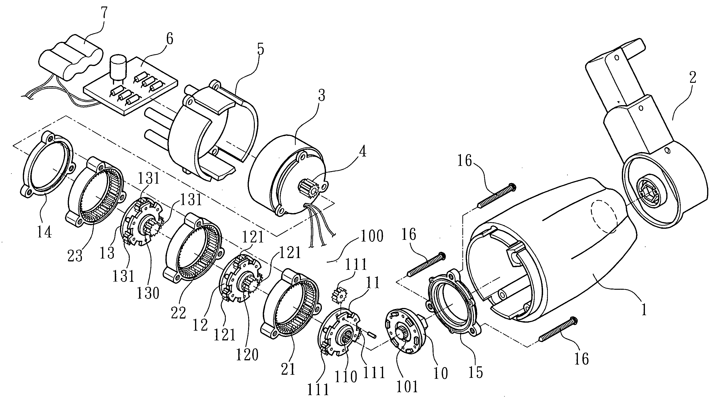
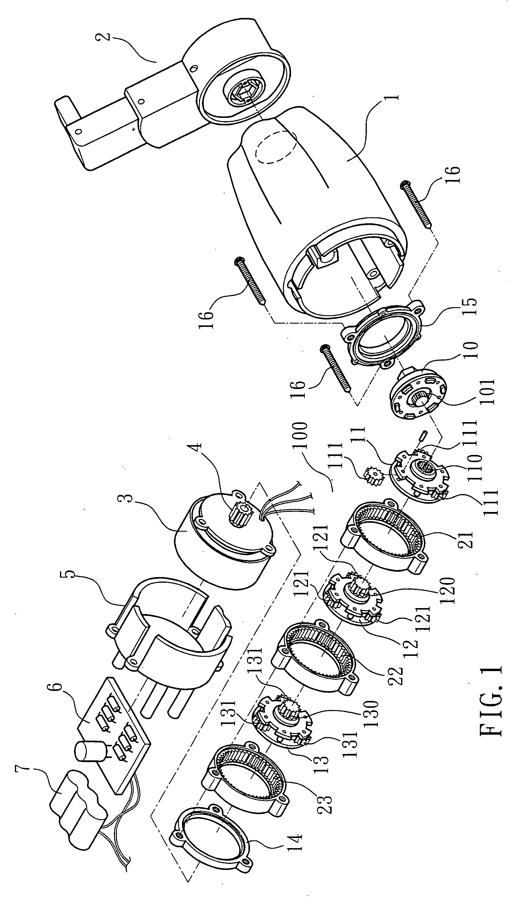
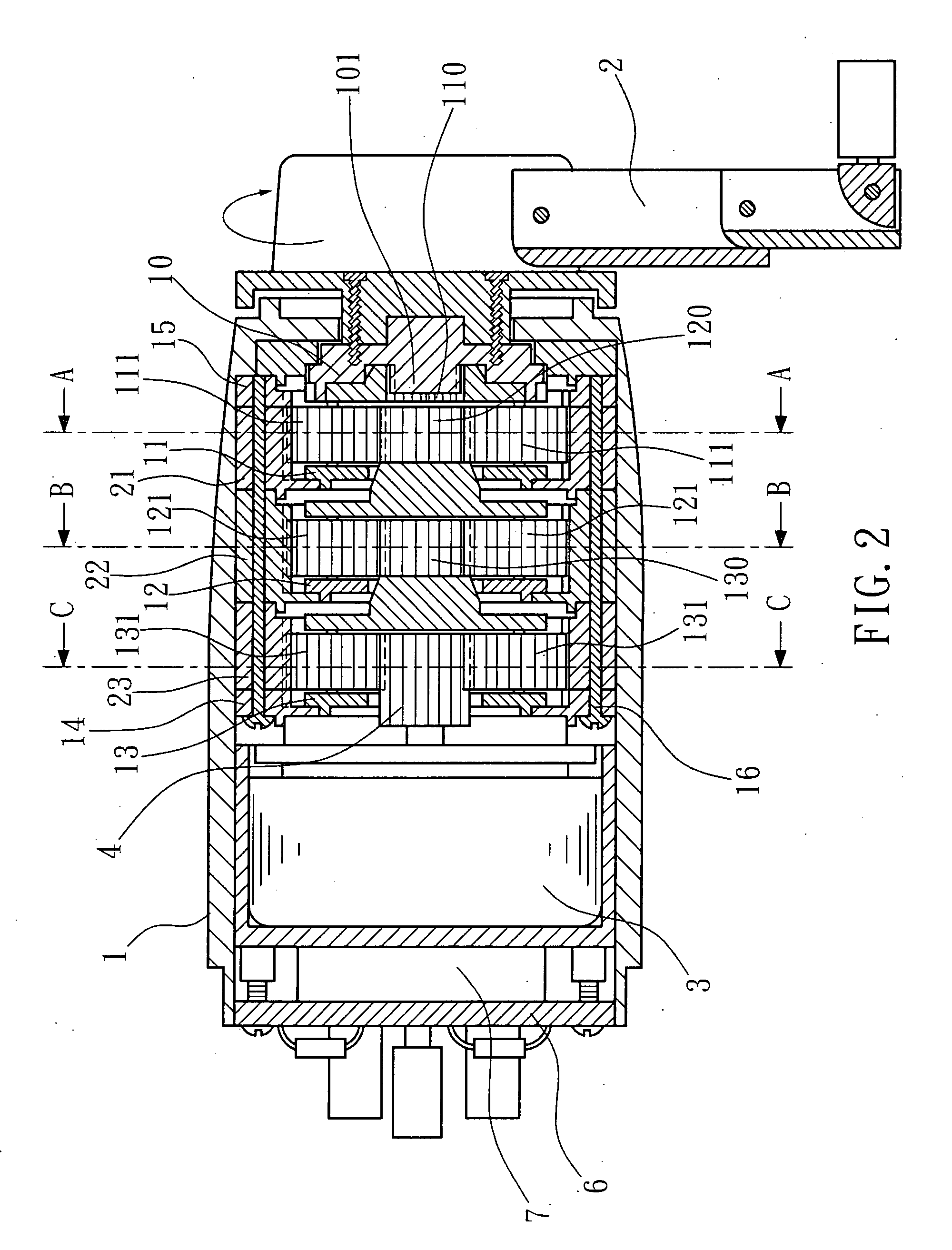
[0011]Referring to FIGS. 1, 2, 3A, 3B and 3C, a hand-driven power generator is shown comprising a housing 1, a power generating unit 3 mounted inside the housing 1 and having a pinion 4 at its input side, a crank handle 2 pivoted to the housing 1 on the outside, a speed change gear mechanism 100 mounted inside the housing 1 and coupled between the pinion 4 of the power generating unit 3 and the crank handle 2, a power rectifier circuit board 6 mounted outside the housing 1 and electrically connected to the power generator unit 3, and a storage battery 7 mounted outside the housing 1 and electrically connected to the power rectifier circuit board 6.

[0012]The speed change gear mechanism 100 comprises a driving wheel 10, a first rotating wheel 11, a first gear ring 21, a second rotating wheel 12, a second gear ring 22, a third rotating wheel 13, a third gear ring 23, two mounting rings 14 and 15, and a plurality of mounting screws 16 that fasten the mounting rings 14 and 15 and the gea...


PUM


Abstract

A cylindrical, high speed change ratio type peed change gear mechanism is disclosed to include a driving wheel rotatable by a crank handle, a first rotating wheel coupled to the driving wheel for synchronous rotation at the same speed and having pivoted small gears spaced around the border and meshed within a first gear ring, a second rotating wheel coupled to the small gears of the first rotating wheel for rotation with the small gears of the first rotating wheel and having pivoted small gears spaced around the border and meshed within a second gear ring, a third rotating wheel coupled to the small gears of the second rotating wheel for rotation with the small gears of the second rotating wheel and having pivoted small gears spaced around the border and meshed with a pinion of a power generating device, and a fixed third gear ring meshed with the small gears of the third rotating wheel.

Description

BACKGROUND OF THE INVENTION[0001]1. Field of the Invention[0002]The present invention relates to a hand-driven power generator and more particularly, to a speed change gear mechanism for hand-driven power generator.[0003]2. Description of the Related Art[0004]A hand-driven power generator has a crank handle for rotation by the user to drive the power generating unit. Because the crank handle is rotated by hand, the speed is limited. Therefore, a speed change gear mechanism is used and coupled between the crank handle and the power generating unit to accelerate the speed. A speed change gear mechanism for a conventional hand-driven power generator is a horizontally extending linking structure, i.e., using a number of gears of different diameters and having the gears meshed with one another at a same elevation. This design of speed change gear mechanism is functional, however it requires much installation space. However, due to the limitation of low speed change ratio, the speed of th...

Claims


Application Information

Patent Timeline
Patent Type & Authority Applications(United States)
IPC IPC(8): F16H57/08F16H37/06
CPCF16H1/46H02K7/1861H02K7/116
Inventor YEN, JEN-YEN
Owner YEN JEN YEN
Why Eureka
Try Eureka