Method of calibrating temperature compensated sensors

a technology of temperature compensation and sensor, applied in the direction of speed measurement using gyroscopic effects, random distribution of objects, static/dynamic balance measurement, etc., can solve the problems of too large variation in sensor characteristics to be able to use a single set of generic calibration parameters, and achieve the effect of reducing the time and cost of individual calibration

Active Publication Date: 2009-03-26
TRANSENSE TECH
View PDF0 Cites 10 Cited by
  • Summary
  • Abstract
  • Description
  • Claims
  • Application Information

AI Technical Summary

Benefits of technology

[0014]The aim of the invented method is therefore to reduce considerably time and cost of individual calibration of the sensors with a large spread of characteristics by means of reduction of the number of temperature calibration points down to one or two.
[0016]A method in accordance with the present invention has the advantage that it enables accurate calibration information to be produced for individual sensors having a large spread of characteristics in a time efficient and therefore cost effective manner.
[0017]Preferably, the measured quantity is torque and the operating condition is temperature, calibration reading for the individual sensor being taken at a small number of different temperatures, in particular at just two temperatures, for each temperature calibration readings being taken at a number of different torques. This has the advantage that the complexity of the calibration procedure is reduced since the number of temperature changes required, which is the time consuming part of the procedure, is reduced.
[0021]In one embodiment, no more than three sets of calibration readings are taken for the individual sensor, each set of readings being taken at one value of the operating condition, the values of the operating condition advantageously spread across the operating range of the sensor, and in particular including one at room (ambient) value, such as ambient temperature, the latter having the particular advantage that minimal heating or cooling of the sensor will be required to take die ambient reading, hence speeding up the process. It has been found to be particularly effective to take just two sets of calibration readings for the individual sensor, each set comprising measured at 3 different values of the measured quantity, by which a good compromise is achieved between time taken to calibrate and accuracy. Applying the method with just a single calibration reading has also been found to produce acceptable results.

Problems solved by technology

This prior art approach is fine in theory but has its practical limitations.
Very often, however, variations in the sensor characteristics are too large to be able to use a single set of generic calibration parameters for all sensors without calibrating them.
The curves are plotted against temperature for the measured torque value M=800 Nm, and show that the maximum error exceeds 100% of reading which is obviously unacceptable.
Bearing in mind that it needs to be done in relatively large number of temperature points, this process considerably increases the sensor cost.
It may even be not feasible in some cases, for instance, if the sensor is installed on a large metal part and needs to be calibrated together with this part.

Method used


Image

  • Method of calibrating temperature compensated sensors
  • Method of calibrating temperature compensated sensors
  • Method of calibrating temperature compensated sensors

Examples


Embodiment Construction

[0027]The steps of a calibration method embodying the invention are described hereinafter in connection with temperature calibration of a SAW based sensor, although it will be understood that the method can also be used for calibrating other parameters effecting readings from a sensor and / or other types of sensor.

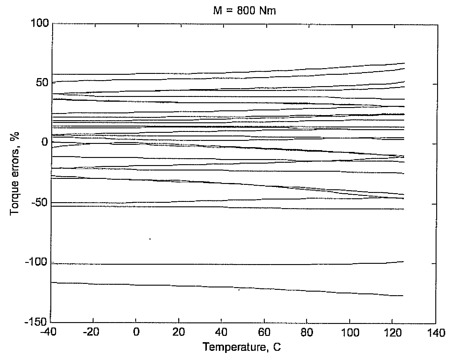
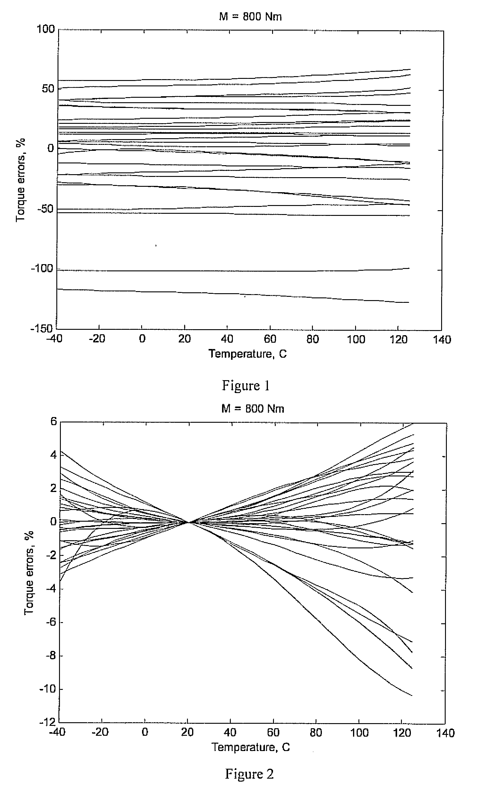
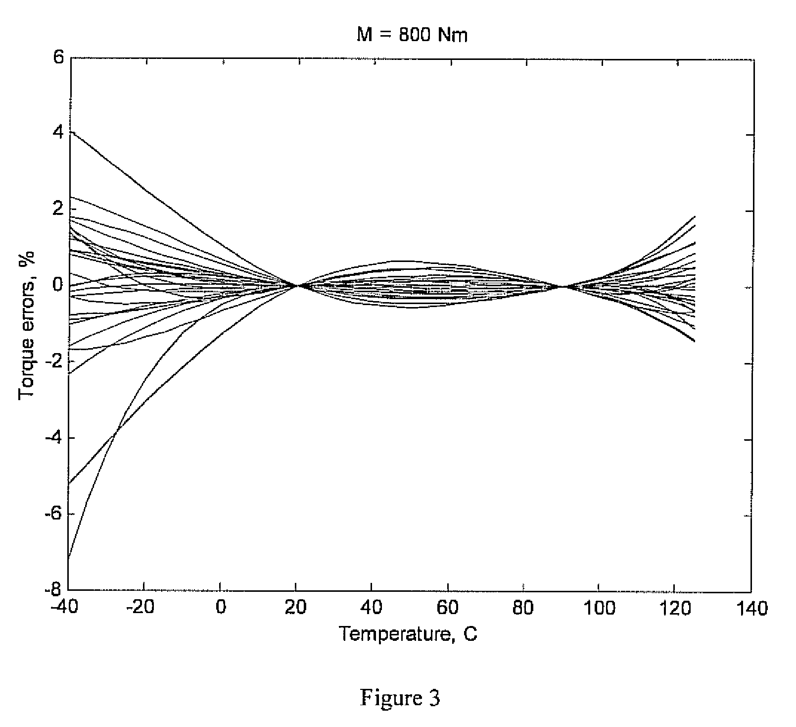
[0028]After developing a high-volume fabrication process for a particular type of a sensor the sensor manufacturer produces and calibrates the first batch of sensors (say, 100 devices to be statistically representative) within the full range of temperatures from Tmin to Tmax in a sufficiently large number of temperature intervals (typically 5 to 10 discrete points).

[0029]This is achieved in practice by heating up or cooling down each individual sensor to a required calibration temperature point Ti (i=1 . . . N) and taking the two readings, Fm and Ft, at a number of predefined values of measured torque value M. In the case of the model described by Eqs. (3) and (4), only thr...


PUM


Abstract

A method of calibrating an individual sensor of a particular sensor type whose output varies non-linearly with at least one measured quantity and at least one operating condition, comprises producing a set of calibration curves for each of a number of sample sensors of the particular sensor type, each curve showing the variation of the sample sensor output with the at least one measured quantity at a different value of the operating condition for the particular sensor type of said individual sensor, said set of curves covering the required operating range for the particular sensor type. The resulting sets of calibration curves of the plurality of sensors derived are then averages and the results used to produce a generic calibration surface for the particular sensor type showing the variation of the sensor reading with the at least one measured quantity across the required operating range. Individual calibration measurements are then taken for a number of different values of the measured quantity for the individual sensor at just a small number of discrete values for the at least one operating condition which fall within the full range of operating values for the at least one operating condition for which the sensor is to be calibrated. The individual calibration readings are then used to map the generic calibration surface to the individual calibration measurements of the individual sensor in order to fit it to the individual sensor.

Description

[0001]This application is a continuation-in-part of U.S. patent application Ser. No. 12 / 035,777 (Attorney Docket No. 148-51), entitled “Method of Calibrating Temperature Compensated Sensors,” filed Feb. 22, 2008, by Kalnin, which is still pending and which is incorporated by reference herein.BACKGROUND OF THE INVENTION[0002]1. Field of the Invention[0003]The present application relates to methods for calibrating sensors for measuring physical parameters in which reading of the sensor varies depending upon conditions such as temperature, so that compensation of the reading from the sensor must be done in order to obtain an accurate value for the measured parameter, and more particularly to calibrating such sensors whose output depends non-linearly on a measured quantity (torque) and on an operating condition (temperature).[0004]2. The Prior Art[0005]The application deals with physical sensors for measuring such quantities as mechanical strain, force, acceleration, pressure, torque, e...

Claims


Application Information

Patent Timeline
Patent Type & Authority Applications(United States)
IPC IPC(8): G01D18/00
CPCG01D18/008G01N29/30G01N2291/02491G01N29/449G01N29/326
Inventor KALININ, VICTOR ALEXANDROVICH
Owner TRANSENSE TECH
Why Eureka
Try Eureka