Inspection hole structure for flash-smelting furnace

a technology of inspection hole and flash furnace, which is applied in the direction of furnaces, blast furnace components, furnace types, etc., can solve the problems of gas leakage from the gap, difficult peeling of slag from the inspection hole frame, and growing slag adhesion to the castabl

Active Publication Date: 2009-04-02
PAN PACIFIC COPPER CO LTD
View PDF2 Cites 9 Cited by
  • Summary
  • Abstract
  • Description
  • Claims
  • Application Information

AI Technical Summary

Benefits of technology

[0018]Accordingly, it is an object of the present invention to provide an inspection hole structure for a flash smelting furnace,

Problems solved by technology

(1) Deposition of slag from the leading end of the concentrate burner onto the inspection hole frame results in exposure of the castable from outside of the frame due to melting loss of the lowermost portion of the inspection hole frame made of a steel sheet by a high temperature, and slag adhering to this castable grows;
(2) Because of (1) above, it is difficult to peel slag deposit off the inspection hole frame; and furthermore,
(3) The sla

Method used


Image

  • Inspection hole structure for flash-smelting furnace
  • Inspection hole structure for flash-smelting furnace
  • Inspection hole structure for flash-smelting furnace

Examples


embodiment 1

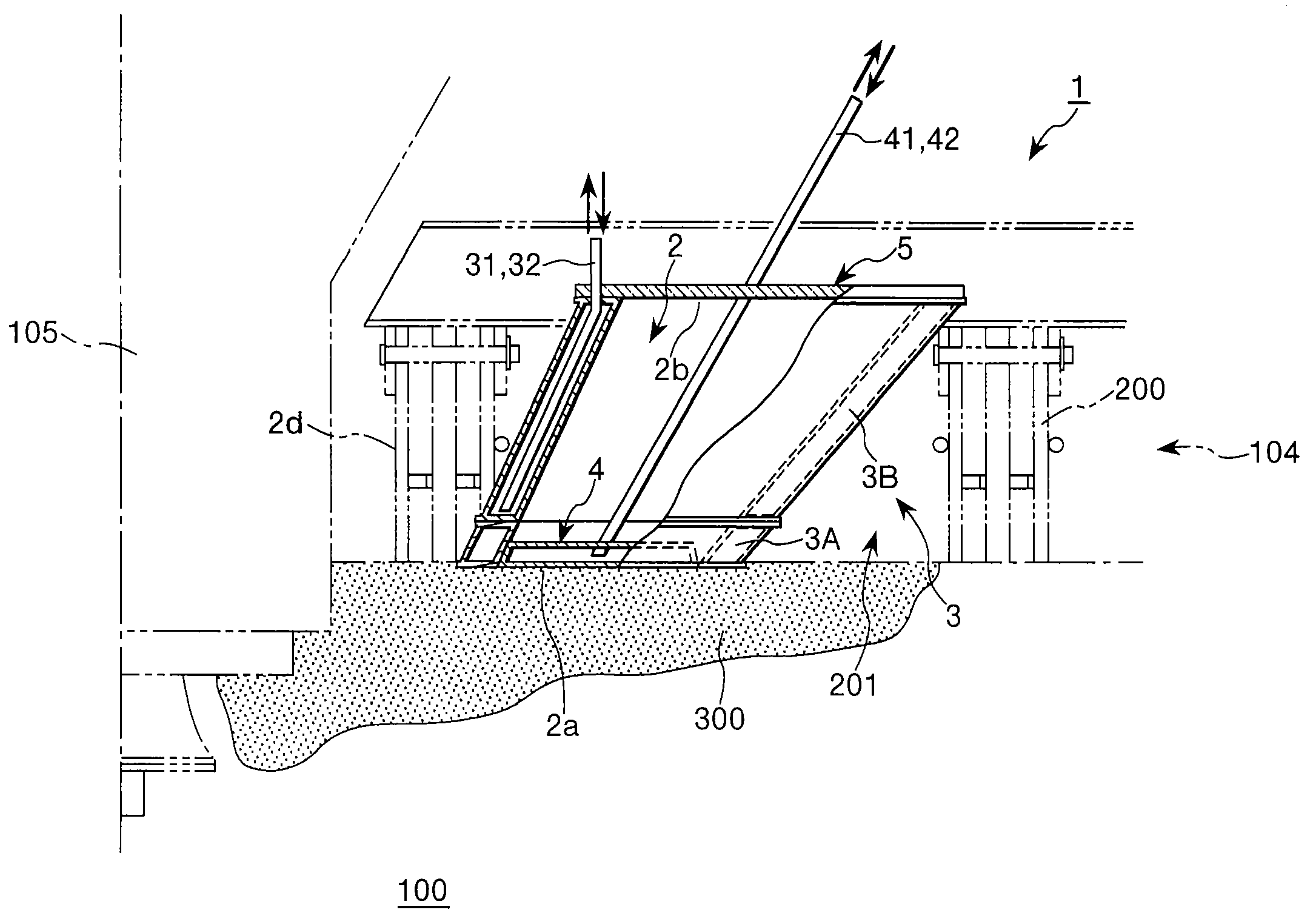
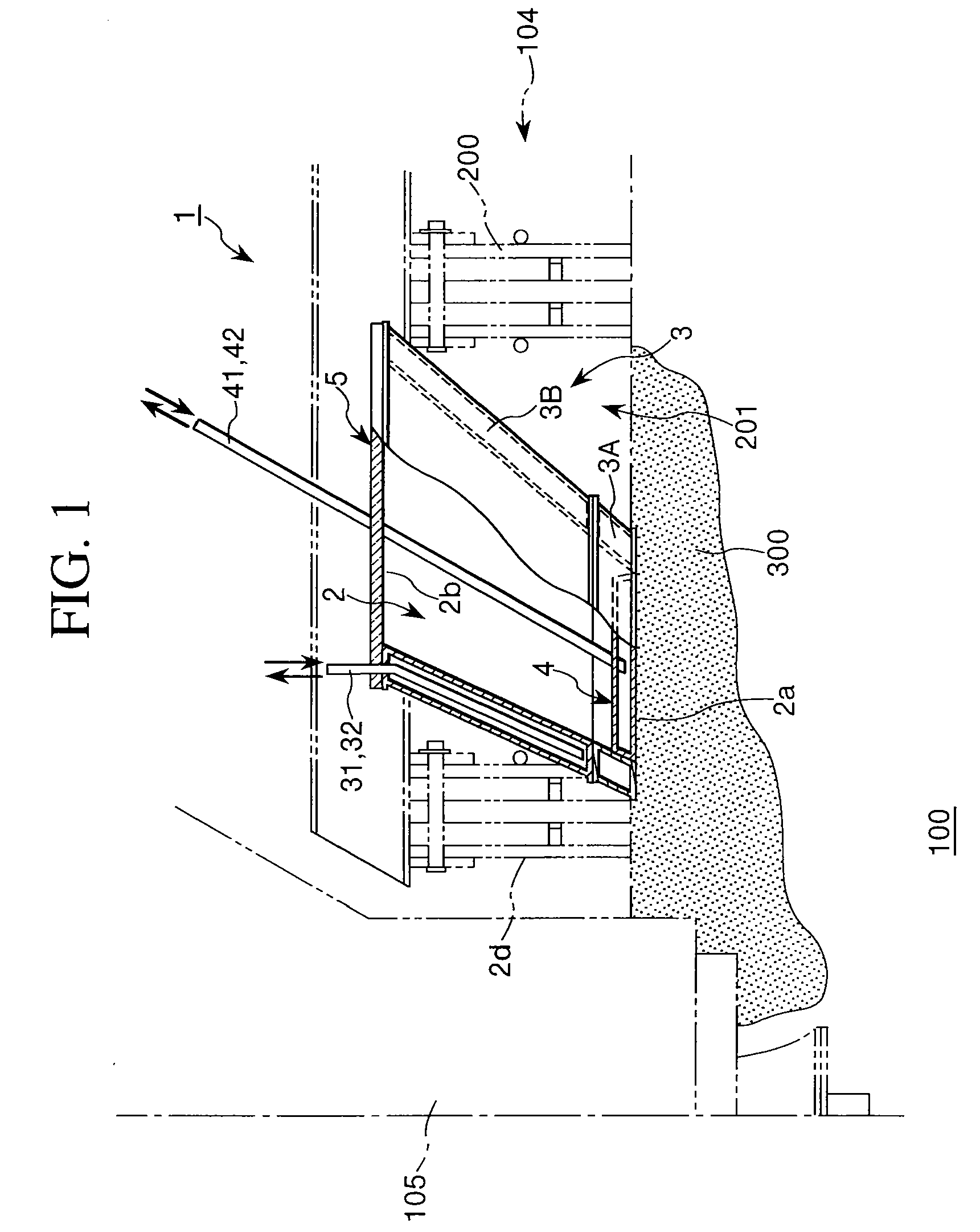
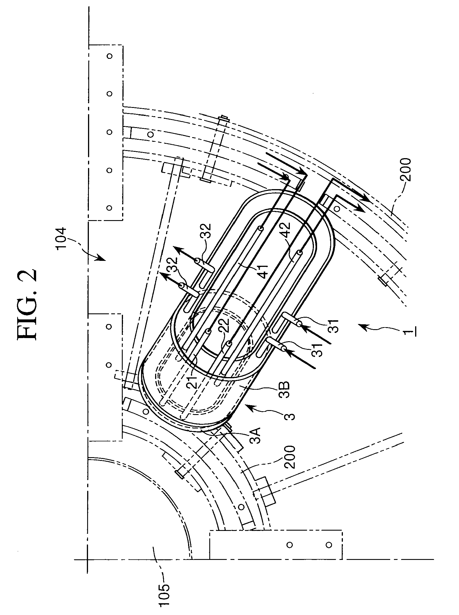
[0033]A schematic configuration of an embodiment of the inspection hole structure for a flash smelting furnace of the present invention is illustrated in FIGS. 1 to 3.

[0034]According to this embodiment, an inspection hole structure 1 forming a furnace inspection hole of a flash smelting furnace is provided adjacent to a concentrate burner 105 installed on a ceiling 104 of a reaction shaft.

[0035]The inspection hole structure 1 is attached to an attachment opening 201 provided on a ceiling 104 of a reaction shaft formed by an attachment frame 200 or the like. Since the manner of attachment of the inspection hole structure 1 to the ceiling 104 is the same as in the conventional art, the details thereof is not shown.

[0036]According to this embodiment, the inspection hole structure 1 has an entire shape comprising a hollow, for example, cylindrical water-cooling jacket 3 (3A, 3B) having a through-opening (i.e., a flash smelting furnace inspection hole) 2 formed at the center thereof. The...


PUM


Abstract

An inspection hole structure 1 forming a furnace inspection hole 2 installed on the reaction shaft ceiling of a flash smelting furnace, comprising a lower-stage water-cooling jacket 3A having an opening 3Aa at the center; an upper-stage water-cooling jacket 3B which is connected integrally to an upper part of said lower-stage water-cooling jacket 3A and forms said inspection hole 2 at the center in cooperation with said lower-stage water-cooling jacket 3A; and a bottom cover water-cooling jacket 4 provided in said lower-stage water-cooling jacket 3A to open or close said opening of said lower-stage water-cooling jacket 3A.

Description

BACKGROUND OF THE INVENTION[0001]1. Field of the Invention[0002]The present invention relates to an inspection hole structure which is installed on the reaction shaft ceiling of a flash smelting furnace and forms a furnace interior inspection hole. More particularly, the invention relates to an inspection hole structure for a flash smelting furnace, which has a water-cooling jacket structure.[0003]2. Description of the Related Art[0004]The flash smelting furnace is one of the conventionally available non-ferrous metal smelting furnaces using sulfide concentrate as a raw material. As shown in FIG. 4, the flash smelting furnace 100 comprises a reaction shaft 101, a settler 102 and an up-take 103. A concentrate burner 105 is installed in the reaction shaft 101 on the ceiling 104 thereof.[0005]The concentrate is blown into the furnace through a concentrate burner 105. The flash smelting furnace 100 utilizes the oxidation reaction heat of the concentrate. In the case where the oxidation ...

Claims


Application Information

Patent Timeline
IPC IPC(8): C21B7/24
CPCF27D21/02
Inventor TSUCHIE, YASUHIROOHNO, MASAKAZUMIYAMOTO, KENJIWAKAYAMA, MASAHIRO
Owner PAN PACIFIC COPPER CO LTD
Why Eureka
Try Eureka