Zoom lens system, optical apparatus, and method for manufacturing zoom lens system

a technology of zoom lens and optical apparatus, which is applied in the field of zoom lens system, optical apparatus, and method for manufacturing zoom lens system, can solve the problems of difficult rapid focus, and conventional zoom lens cannot achieve excellent optical performance without, and achieve excellent optical performan

Inactive Publication Date: 2009-04-02
NIKON CORP
View PDF16 Cites 61 Cited by
  • Summary
  • Abstract
  • Description
  • Claims
  • Application Information

AI Technical Summary

Benefits of technology

[0011]The present invention is made in view of above described problems and has an object to provide a zoom lens system capable of focusing quickly, having excellent optical performance even upon vibration reduction, an optical apparatus using the zoom lens system, and a method for manufacturing the zoom lens system.
[0016]According to a fifth aspect of the present invention, there is provided a method for manufacturing a zoom lens system comprising steps of: disposing, in order from an object, a first lens group having positive refractive power, and a second lens group, a third lens group; disposing an N-th lens group to an image side of the third lens group; varying a distance between the first lens group and the second lens group, and a distance between the second lens group and the third lens group upon zooming from a wide-angle end state to a telephoto end state; moving the third lens group along an optical axis of the zoom lens system upon focusing from an infinity object to a close object; and moving at least a portion of the N-th lens group in a direction perpendicular to the optical axis upon vibration reduction.
[0019]The present invention makes it possible to provide a zoom lens system having a vibration reduction function capable of performing quick focusing with excellent optical performance even upon vibration reduction, an optical apparatus equipped therewith, and a method for manufacturing the zoom lens system.

Problems solved by technology

Accordingly, the focusing lens group becomes large and heavy, so that it has been difficult to focus rapidly.
Moreover, the conventional zoom lens cannot be accomplished excellent optical performance without sufficiently correcting aberrations upon vibration reduction.

Method used


Image

  • Zoom lens system, optical apparatus, and method for manufacturing zoom lens system
  • Zoom lens system, optical apparatus, and method for manufacturing zoom lens system
  • Zoom lens system, optical apparatus, and method for manufacturing zoom lens system

Examples


first embodiment

[0052]A zoom lens system having a vibration reduction function according to a first embodiment is explained below.

[0053]A zoom lens system according to the first embodiment includes, in order from an object, a first lens group having positive refractive power, a second lens group having negative refractive power, a third lens group having positive refractive power, and a fourth lens group having positive refractive power. Upon zooming from a wide-angle end state to a telephoto end state, the second lens group and the third lens group are moved. With this configuration, it becomes advantageous to make the zoom mechanism simple.

[0054]Upon focusing from an infinity object to a close object, the third lens group is moved along the optical axis. With focusing by the third lens group, which is small and compact, it becomes possible to carry out quick focusing.

[0055]In the fourth lens group, at least a portion of the lens group is moved as a vibration reductioN-th lens group in a direction...

example 1

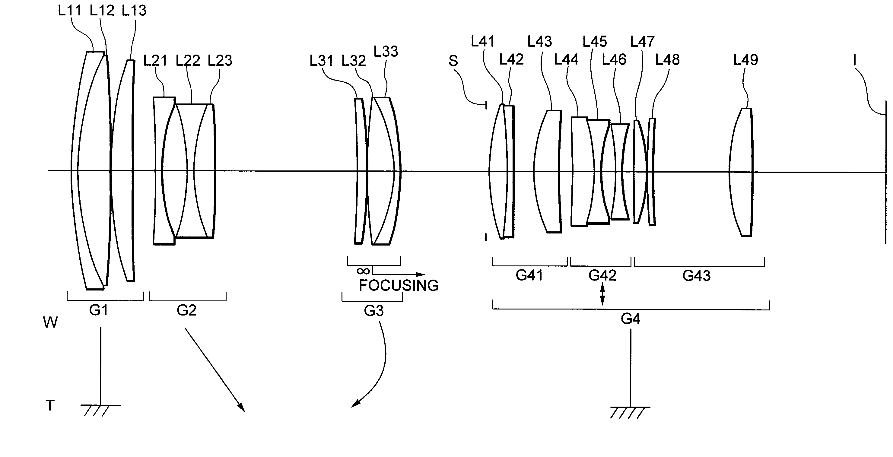
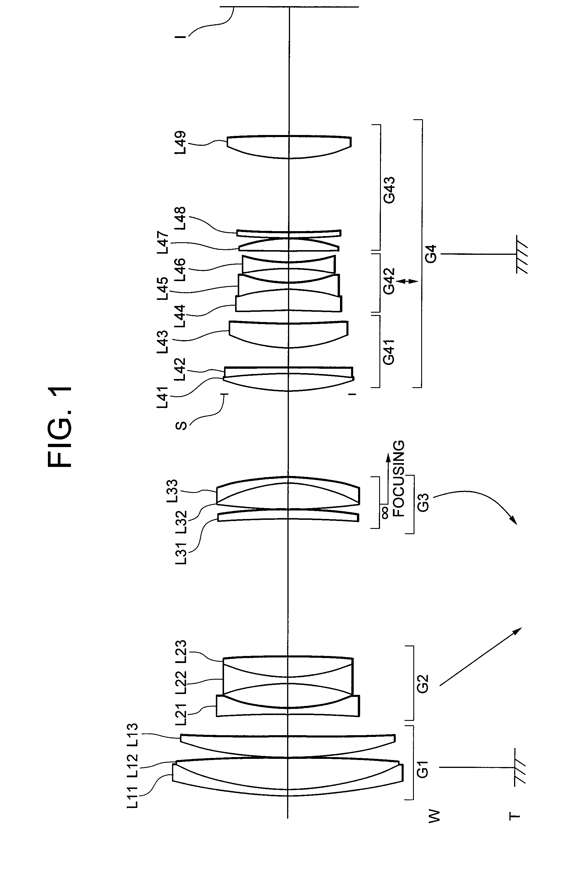
[0093]FIG. 1 is a sectional view showing a lens configuration of a zoom lens system having a vibration reduction function according to Example 1 of a first embodiment.

[0094]In FIG. 1, the zoom lens system having a vibration reduction function is composed of, in order from an object, a first lens group G1 having positive refractive power, a second lens group G2 having negative refractive power, a third lens group G3 having positive refractive power, and a fourth lens group G4 having positive refractive power. Upon zooming from a wide-angle end state (W) to a telephoto end state (T), the second lens group G2 moves to the image plane I side, the third lens group G3 moves at first to the image plane I side and then to the object side, and the first lens group G1 and the fourth lens group G4 are fixed such that a distance between the first lens group G1 and the second lens group G2 increases, and a distance between the second lens group G2 and the third lens group G3 decreases.

[0095]The ...

example 2

[0119]FIG. 6 is a sectional view showing a lens configuration of a zoom lens system having a vibration reduction function according to Example 2 of the first embodiment.

[0120]In FIG. 6, the zoom lens system having a vibration reduction function is composed of, in order from an object, a first lens group G1 having positive refractive power, a second lens group G2 having negative refractive power, a third lens group G3 having positive refractive power, and a fourth lens group G4 having positive refractive power. Upon zooming from a wide-angle end state (W) to a telephoto end state (T), the second lens group G2 moves to the image plane I side, the third lens group G3 moves at first to the image plane I side and then to the object side, and the first lens group G1 and the fourth lens group G4 are fixed such that a distance between the first lens group G1 and the second lens group G2 increases, and a distance between the second lens group G2 and the third lens group G3 decreases.

[0121]Th...


PUM


Abstract

Providing a zoom lens system having a vibration reduction function capable of performing quick focusing with excellent optical performance even upon vibration reduction. The system including, in order from an object, a first lens group G1 having positive refractive power, a second lens group G2 having negative refractive power, a third lens group G3 having positive refractive power, and a fourth lens group G4 having positive refractive power. Upon zooming from a wide-angle end state to a telephoto end state, a distance between the first lens group G1 and the second lens group G2 varies, and a distance between the second lens group G2 and the third lens group G3 varies. The third lens group G3 carries out focusing from an infinity object to a close object. At least a portion of the fourth lens group G4 moves in a direction perpendicular to the optical axis.

Description

[0001]The disclosure of the following priority applications are herein incorporated by reference:[0002]Japanese Patent Application No. 2007-258973 filed on Oct. 2, 2007; and[0003]Japanese Patent Application No. 2007-331499 filed on Dec. 25, 2007.BACKGROUND OF THE INVENTION[0004]1. Field of the Invention[0005]The present invention relates to a zoom lens system suitable for a single-lens reflex camera using a film or a solid-state imaging device, an optical apparatus using the same, and a method for manufacturing the zoom lens system.[0006]2. Related Background Art[0007]There has been proposed a large aperture zoom lens as a high zoom ratio zoom lens having a vibration reduction function such as Japanese Patent Application Laid-Open Nos. 2003-344766 and 2006-201524.[0008]However, such a conventional zoom lens having a low zoom ratio has a four-lens configuration that is a first lens group having positive refractive power,[0009]a second lens group having negative refractive power, a th...

Claims


Application Information

Patent Timeline
Patent Type & Authority Applications(United States)
IPC IPC(8): G02B27/64G02B15/16
CPCG02B27/646G02B15/173G02B15/144113
Inventor MIZUGUCHI, KEIKOITO, TOMOKI
Owner NIKON CORP
Why Eureka
Try Eureka