Lighting system with removable light modules

a technology of light modules and lighting systems, applied in the field of light systems, can solve the problems of large size, additional design and production costs, and light fixtures that are not easily visible, and achieve the effect of improving lighting systems

Active Publication Date: 2009-04-02
ABL IP HLDG
View PDF10 Cites 125 Cited by
  • Summary
  • Abstract
  • Description
  • Claims
  • Application Information

AI Technical Summary

Benefits of technology

[0007]Another object of the invention is to enhance lightin

Problems solved by technology

While these systems are flexible, they have disadvantages.
One disadvantage is that they are relatively large in the sense that the light fixtures are conspicuous.
In applications where the appearance of the lighting system itself contributes to its overall aesthetics, there are additional

Method used


Image

  • Lighting system with removable light modules
  • Lighting system with removable light modules
  • Lighting system with removable light modules

Examples


Embodiment Construction

[0024]For a better understanding of the present invention together with other and further objects, advantages, and capabilities thereof, reference is made to the following disclosure and appended claims taken in conjunction with the above-described drawings.

[0025]For purposes herein, the following definitions apply. A “removable light module” means a light module that may be mounted on, removed from, or relocated on the frame manually without use of tools or need for permanent manipulated electrical connections, such as a connection made with a screw, splice, wire nut, etc. The term “magnetic material” means a material that is either a permanent magnet or a material that is strongly attracted by a permanent magnet. A phrase stating that an article is mounted on a surface of an object includes an arrangement wherein the article is mounted within the object such that a surface of the article comprises or coincides with a portion of the surface of the object. The term “LED” means light...


PUM


Abstract

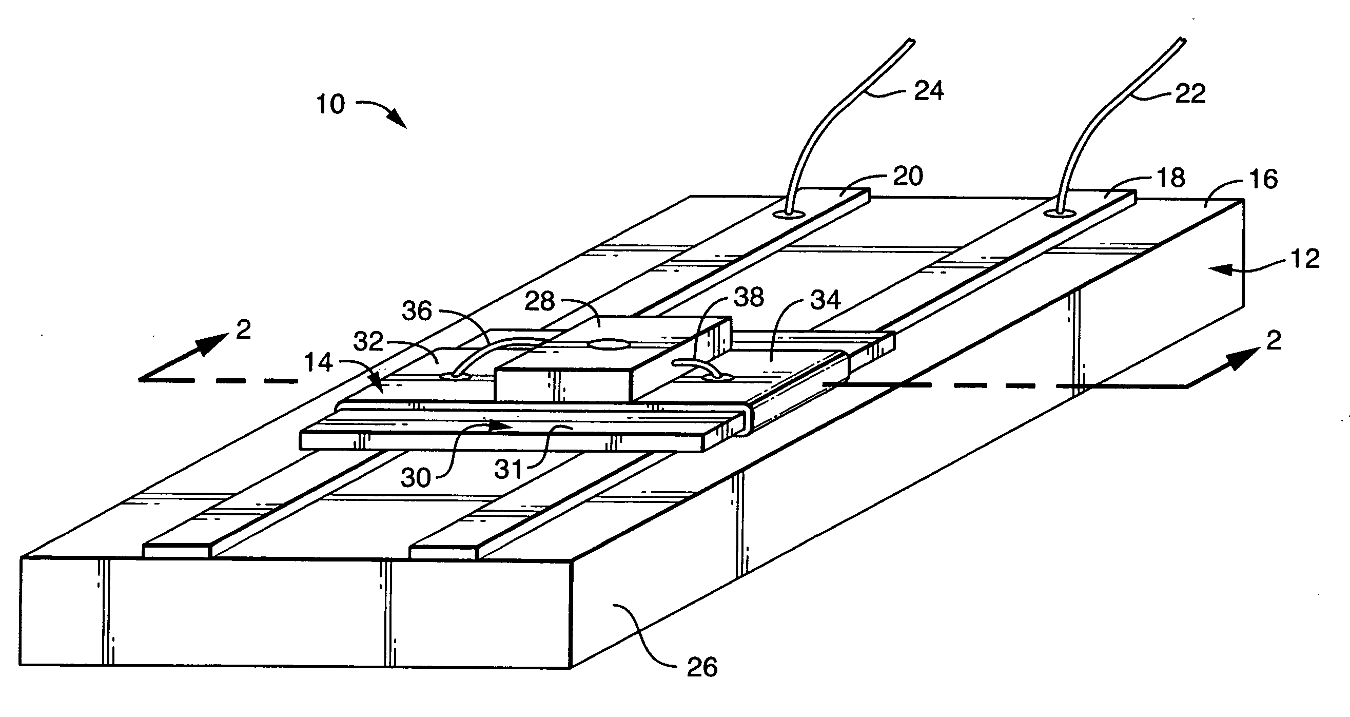
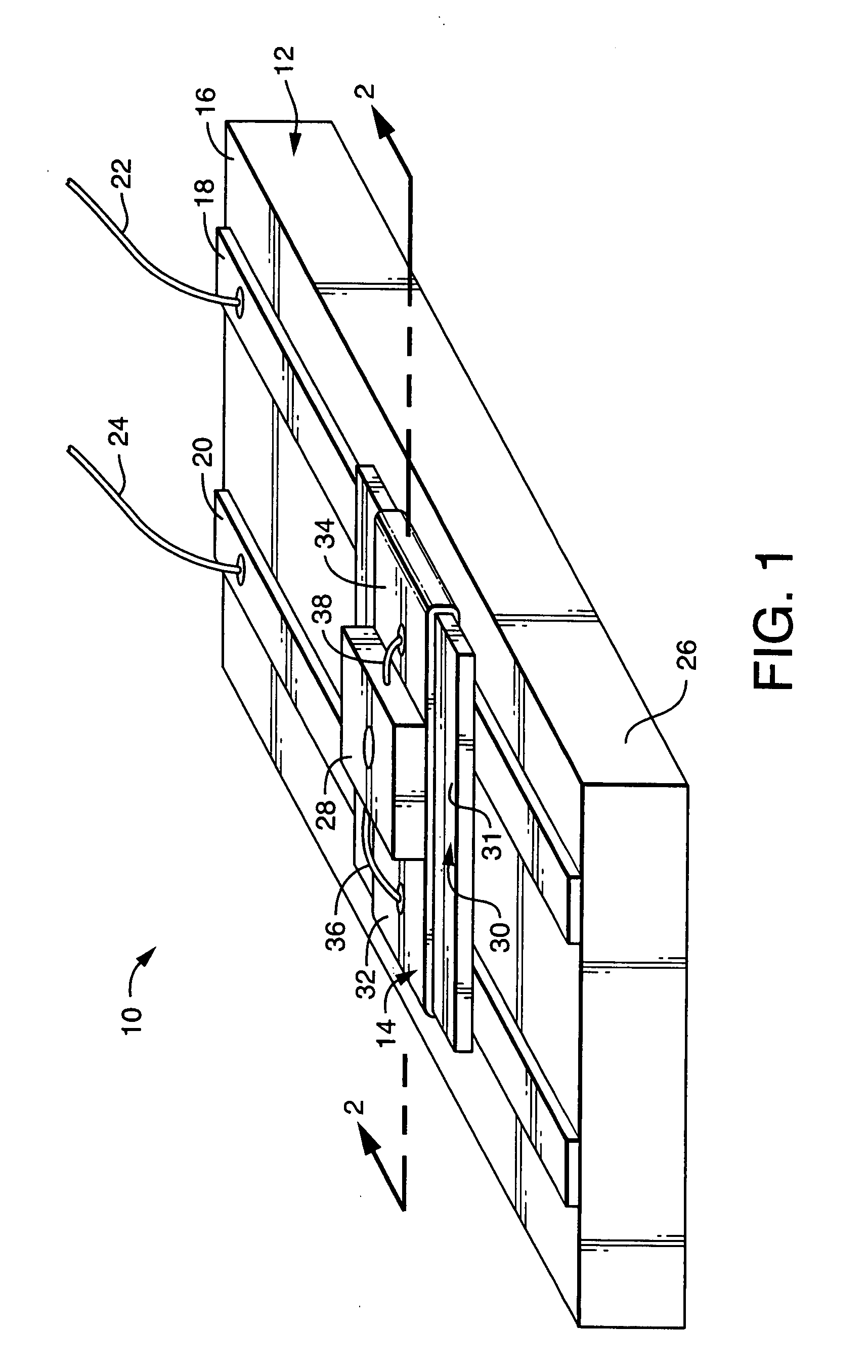
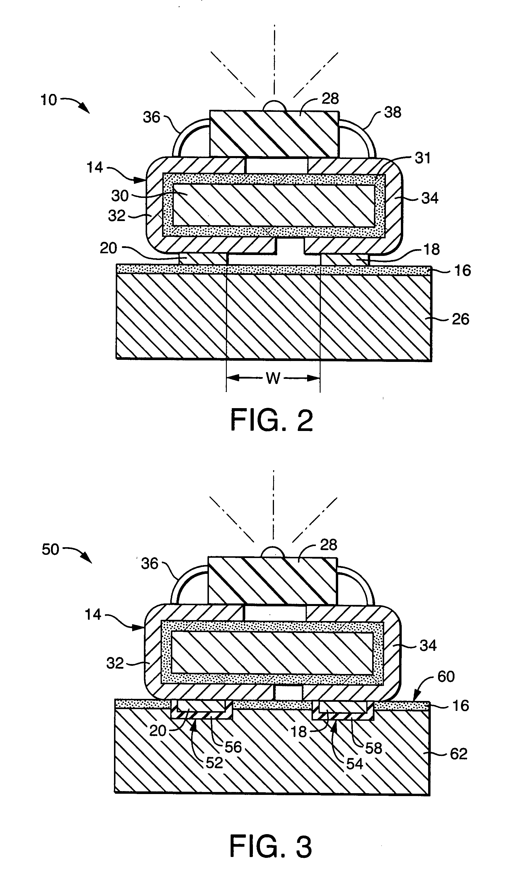
A lighting system with removable light modules mounted on a frame by an attractive force between magnetic material of the light module and magnetic material of the frame such that a light module may be installed on, removed from, or relocated on the frame manually without tools or permanent electrical connection. The frame may be one-, two-, or three-dimensional, and it may provide an aesthetic appearance even when the lighting system is not illuminated. The light modules may employ incandescent, quartz-halogen, LED, or fluorescent light sources. Particularly, in LED embodiments, the magnetic materials serve the dual functions of mounting and heat sinking. The lighting system may be utilized as a sign, signaling device, or a building block in larger lighting systems. The lighting system has a wide variety of applications and provides a user with improved ability to control the quantity, direction, and characteristics of the emitted light.

Description

BACKGROUND OF THE INVENTION[0001]1. Field of the Invention.[0002]This invention relates to lighting systems and more particularly to lighting systems having manually insertable and removable light modules such that the quantity, direction, and / or characteristics of the light emitted from the system may readily be varied.[0003]2. Background Art.[0004]In modern lighting systems, it is desirable to have a great deal of flexibility in the user's ability to control the quantity, direction, and characteristics of the light emitted from the system. In theater settings, one is accustomed to observing a number of light fixtures capable of directing light of varying intensities, color, and other characteristics onto the stage. In commercial settings, adjustable reflector lamps and track lights are frequently employed to illuminate merchandise or displays. In office and residential settings, track lights are typically used to direct light to a particular work area or for visual effect. While t...

Claims


Application Information

Patent Timeline
IPC IPC(8): H01R33/00F21V13/04F21V21/096F21V21/00F21V29/00F21K7/00F21V7/00F21K99/00
CPCA47F3/001F21S2/00F21S2/005F21S8/038F21S8/066F21V21/096F21V29/004F21V25/04F21W2131/405F21Y2101/02H01R13/6205H01R25/147F21V21/35F21Y2115/10F21V29/70
Inventor SANROMA, JOHN P.MITCHELL, JR., JOHN D.
Owner ABL IP HLDG
Why Eureka
Try Eureka