

Testing dynamically addressed network devices
Patent Information
- Authority / Receiving Office
- US · United States
- Current Assignee / Owner
- VERIZON PATENT & LICENSING INC
- Publication Date
- 2009-04-02
- Estimated Expiration
- Not applicable · inactive patent
Smart Images
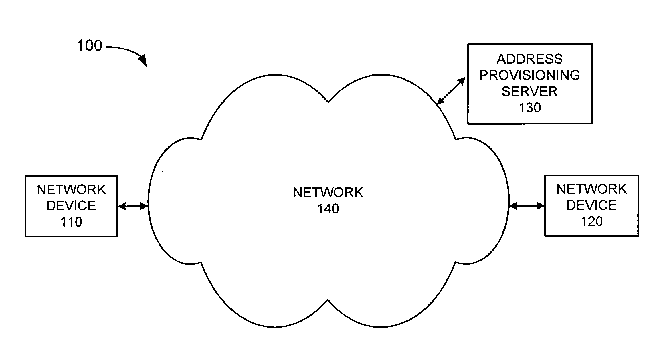
Figure 1 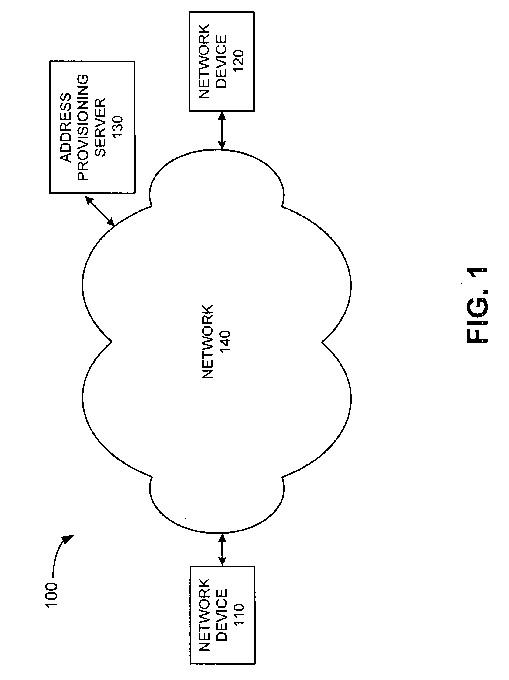
Figure 2 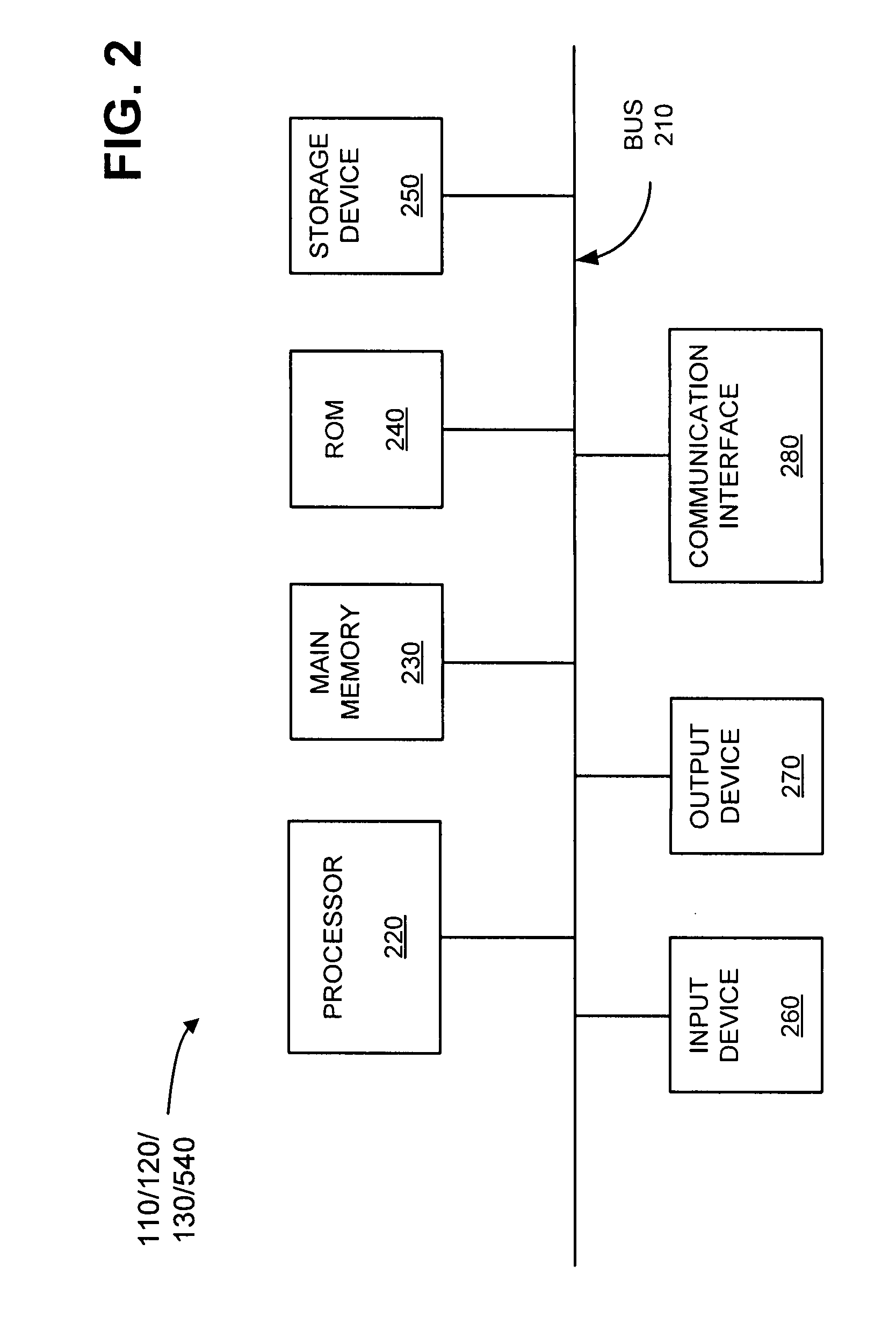
Figure 3
Abstract
Description
[0001] Durability and reliability in today's data networks is of utmost importance. Accordingly, active performance testing of such networks is routinely conducted in which two test end points exchange test data streams. Unfortunately, dynamic address provisioning of network devices significantly impairs a network operator's ability to easily and efficiently test such network devices.BRIEF DESCRIPTION OF THE DRAWINGS
[0002] FIG. 1 illustrates an exemplary network in which systems and methods described herein may be implemented;
[0003] FIG. 2 depicts an exemplary network device configured to communicate via the exemplary network illustrated in FIG. 1;
[0004] FIG. 3 is a flow diagram illustrating exemplary processing associated with establishing a testing environment between a statically addressed network device and a dynamically addressed network device of FIG. 1;
[0005] FIG. 4 is a block diagram illustrating an exemplary test setup message;
[0006] FIG. 5 is a block diagra...